4,908 views ·
42 replies
5k views
42 replies
Yet another steel beam thread, but with a twist!
I should have copies of their drawings somewhere... I knew where they were 2 years ago, but that doesn't help me much now since they've changed places since thenJ justusandersson said:

I'll go on a treasure hunt tomorrow!
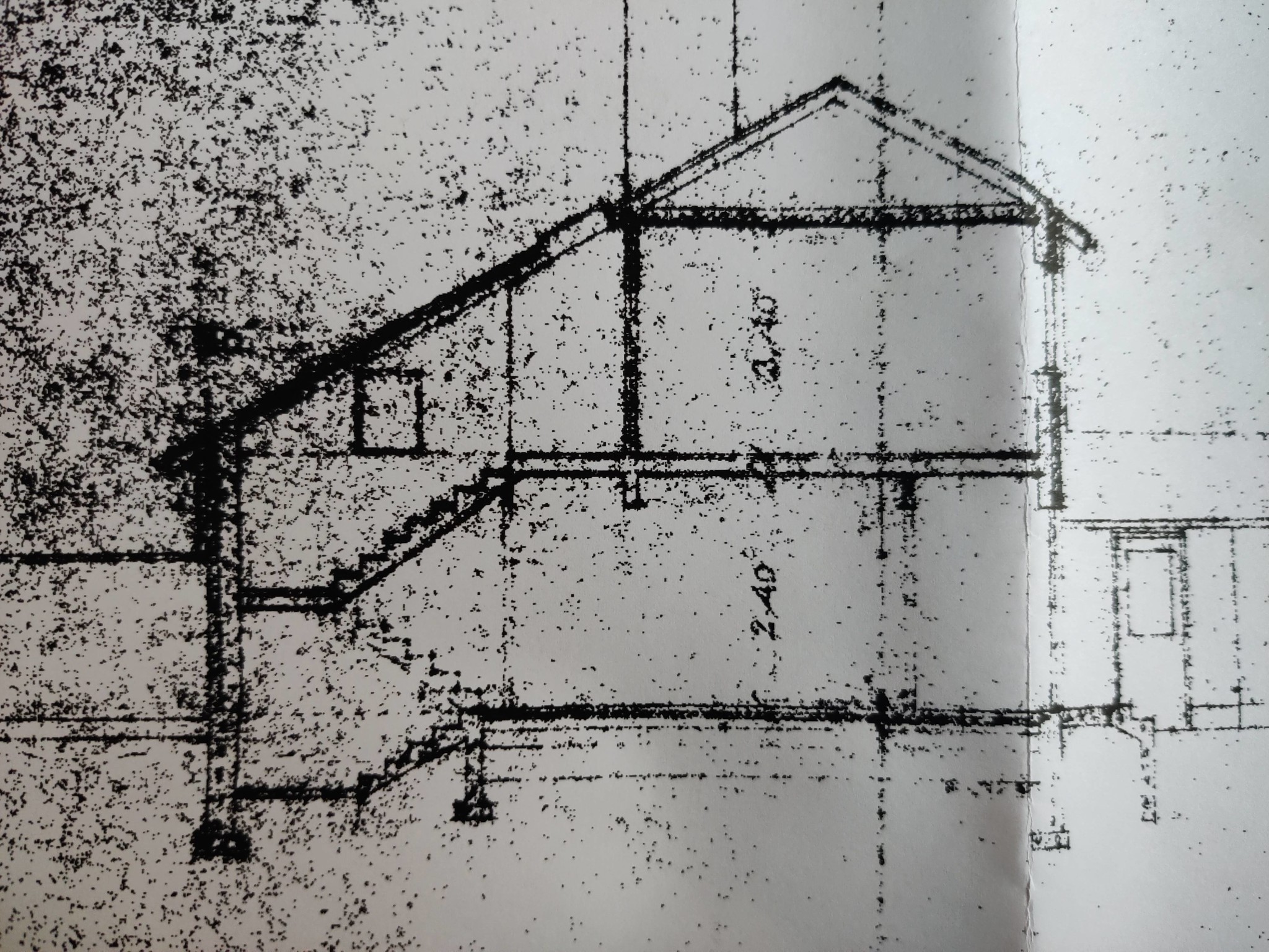
Went on the treasure hunt and found this.
These are the drawings that were submitted to the municipality. However, they are not entirely accurate with reality as the beam visible on the lower floor in the ceiling doesn't exist IRL, nor does the half-staircase down under the landing staircase. Thus, I find it hard to see that the "foundation beam/element" or whatever you want to call it by that staircase exists either. Otherwise, they probably match pretty well.
In the foundation/slab, I can see the following when I measure.
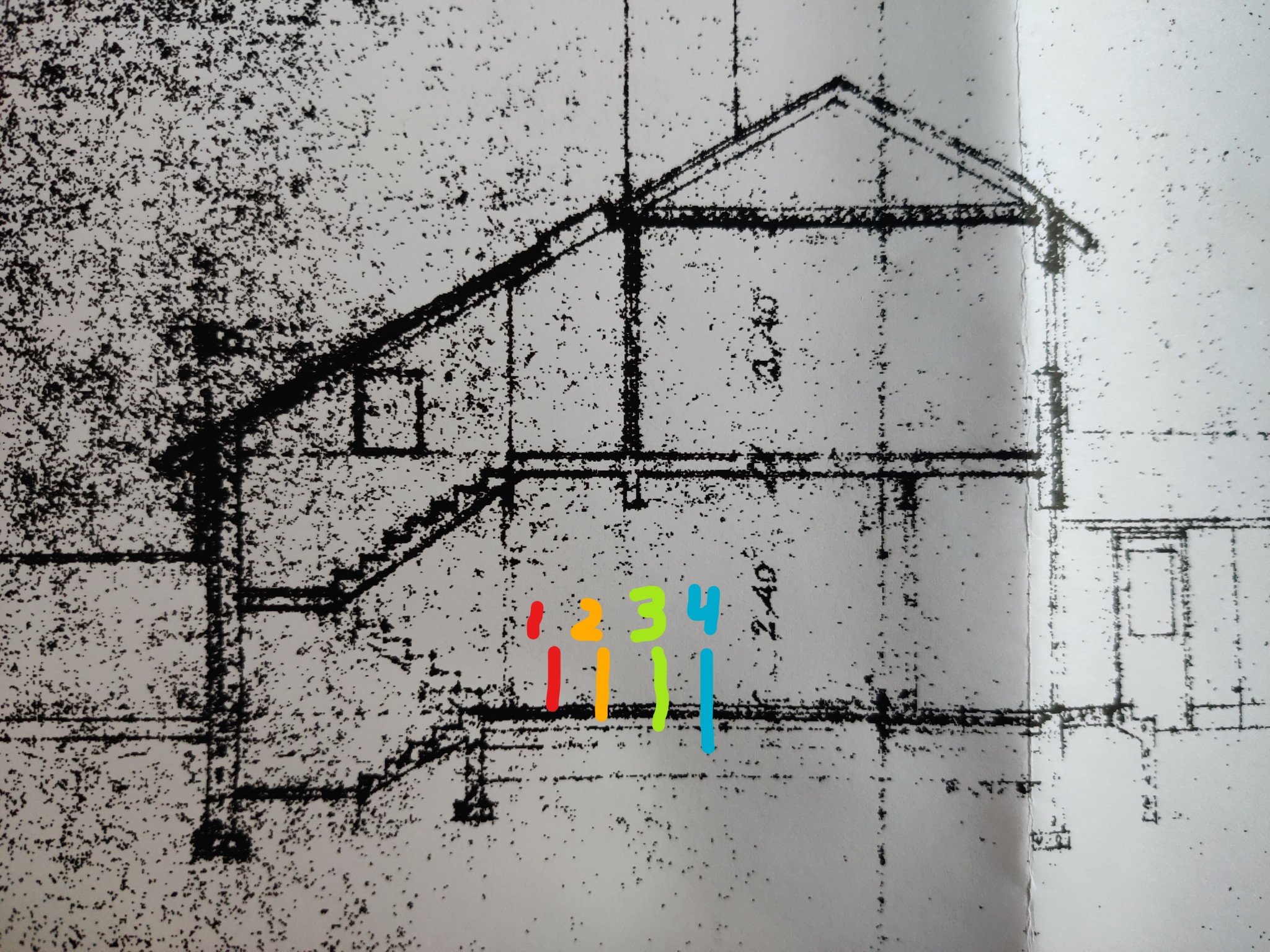
Layer 1 = 10 cm .............................Floor covering/surface layer??
Layer 2 = 10-15 cm .........................Footing/slab??
Layer 3 = 20 cm .............................Insulation??
Layer 4 = 40-45 cm ........................Drainage material??
The foundation beams/elements go down 1.6m and then stand on a base which is (WxH) 60x20 cm.
Did you get any wiser from this @justusandersson?

You might get a little wiser, but not much. The foundation method is clearly what is called spread footings, i.e., footings under all load-bearing walls. The concrete slabs cast between the (likely) walled-up walls that stand on the footings can be unreinforced. For this as well as the order between 1, 2, and 3, one must have either the technical description or a detailed drawing to see. I believe there is insulation since the houses seem to be competently designed. Otherwise, it is not obvious with houses from the relevant period. I would not start chiseling anything away without knowing the situation. The municipality must have drawings.
I wish the municipality had drawings, but unfortunately, they don't as their archive room burned down 20 years ago or something like that. I have tried to sniff out drawings from the municipality before.J justusandersson said:You may become a little wiser, but not much. The foundation method is clearly what is called spread footings, i.e., footings under all bearing walls. The concrete slabs cast between the probably raised walls standing on the footings may be unreinforced. This, as well as the sequence between 1, 2, and 3, requires either the technical description or detailed drawings to see. I believe there is insulation since the houses seem to be competently designed. Otherwise, it is not obvious with houses from the period in question. I wouldn't start chipping away at anything without knowing the situation. The municipality must have drawings.
Regarding insulation, I would also think so; the floors, despite lacking underfloor heating, are not particularly cold to walk on. We have a floor in the garage angle that with 98% certainty is uninsulated, and that floor is considerably colder in the winters.
Right now, I am seriously considering skipping underfloor heating in the rest of the part more than the part that has a raised floor today, mostly due to cost reasons
But that thought will probably change 20 times over if I know us well! Underfloor heating is under ideal conditions (waterborne, embedded in concrete, and heated via a heat pump, etc.) a theoretically appealing solution, but it is a fad. A lot can go wrong along the way. Personally, I would never consider it.
You are not setting small demands on the readers' memory when it has been over a month since the previous post... As a basis for a K-drawing, both a correct description of the current conditions (drawings or measurements) and a construction calculation are required. How much time effort is required for that in this case, I dare not have an opinion on. The best thing is to ask for a quote.
Haha no, I know!J justusandersson said:You're not making small demands on readers' memory, since it's been over a month since the last post... For a K-drawing, both a correct description of the current conditions (drawings or measurements) and a construction calculation are required. How much time is needed for that in this case, I dare not have any opinion on. The best is to ask for a quote.
I'm trying to work quickly, but have been waiting for quotes and they have taken quite a bit of time..
So I took a chance, since you usually have everything under control
But I'm planning to contact a separate engineer today, as I wasn't entirely satisfied with the price I got from the carpenter
Since I am an incurable cost optimist, my estimates rarely match reality. Therefore, I never dare to make bold claims in such matters. The better preparations you have made, the cheaper it will be, that I dare to claim.
Sounds good.J justusandersson said:
I should be able to provide some thorough material once I know what is required.
I know the house inside and out, except for the foundation, but finding out how it's constructed is always possible as I intend to repair and pour a new one in the current living room before opening up the wall, and thus I'll get to see in black and white how the foundation is built
Yeah, being a cost optimist is a bit dangerous, I'm similar in many ways... or I usually have big ambitions but a very limited budget
And I convince myself it's possible to create what I want with that budget. It usually works, but in this case, I'm starting to realize I may be a bit too naive Then hopefully, we have made more progress in the matter.
I have contacted a designer, and he suggests that 100*100 steel columns + a HEA 180 should do the job.
His proposal was also to place the beam inside (in the living room) of the load-bearing wall, so that it can be installed first and then just tear down the wall afterwards.
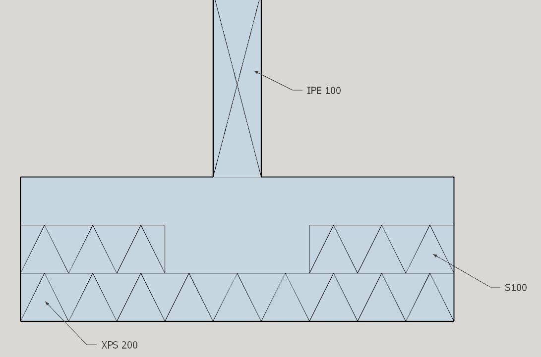
So with that info comes the next question, the slab will need to be reinforced under the columns, but how is a reinforced slab usually dimensioned?
I'm thinking it would be a simple layer of XPS 200 and then ~20cm of concrete. The question, however, is how much larger an area beyond the column's contact surface should be considered?
I should add that the reason I'm asking is that it would help with the planning of the layout by knowing how it's generally done
I have contacted a designer, and he suggests that 100*100 steel columns + a HEA 180 should do the job.
His proposal was also to place the beam inside (in the living room) of the load-bearing wall, so that it can be installed first and then just tear down the wall afterwards.
So with that info comes the next question, the slab will need to be reinforced under the columns, but how is a reinforced slab usually dimensioned?
I'm thinking it would be a simple layer of XPS 200 and then ~20cm of concrete. The question, however, is how much larger an area beyond the column's contact surface should be considered?
I should add that the reason I'm asking is that it would help with the planning of the layout by knowing how it's generally done
Click here to reply