My partner has been trying to persuade and convince me for some time now to "knock down" the wall between the kitchen and the living room in order to rearrange a bit in the layout and get an overall better flow in the house.
So now I'm starting to give in... haha.
BUT, the wall she wants to smack down is, of course, a load-bearing stone wall where both water and electricity run nicely. That is one of the reasons why I've been against it from the start.
However, I want to investigate whether it would even be possible to take down the wall and replace it in a way that I want.
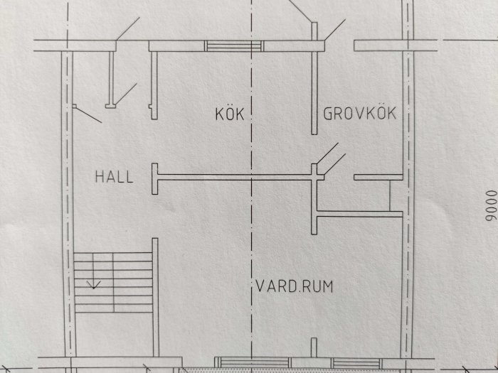
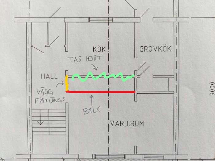
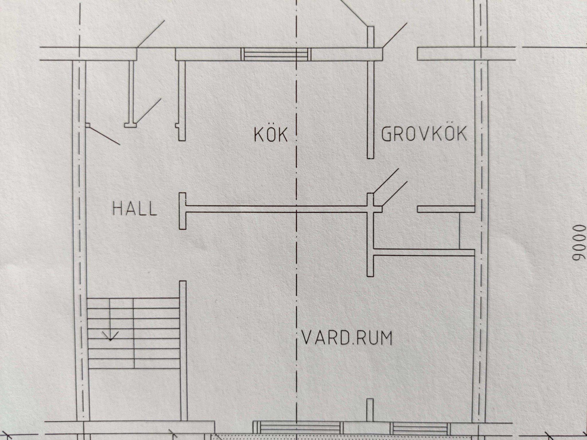
I can start with a picture of the floor plan so you can see which wall it is.
The wall is the one that goes between the kitchen and the living room. However, this is not my floor plan but one of the neighbors, so it is not 100% identical. For example, we no longer have those wall stubs in the corner of the living room.
So, what is my vision then? Well, I want a supporting beam running directly under the "load-bearing wall" on the upper floor (it is not fully load-bearing; if you want to know more, I can clarify).
That is like this:
Are there any issues with moving the support from the original position of the load-bearing wall?
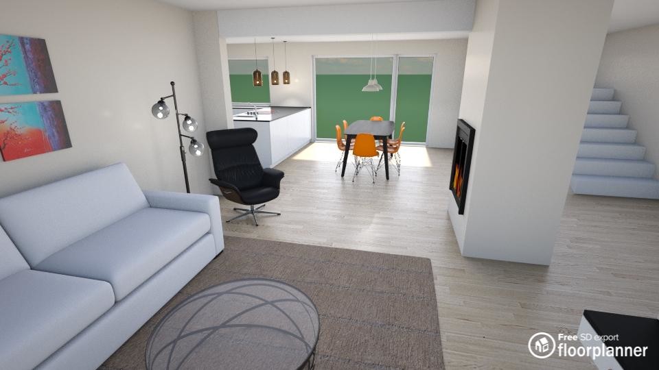
The idea is that the result after the work should look something like this picture:
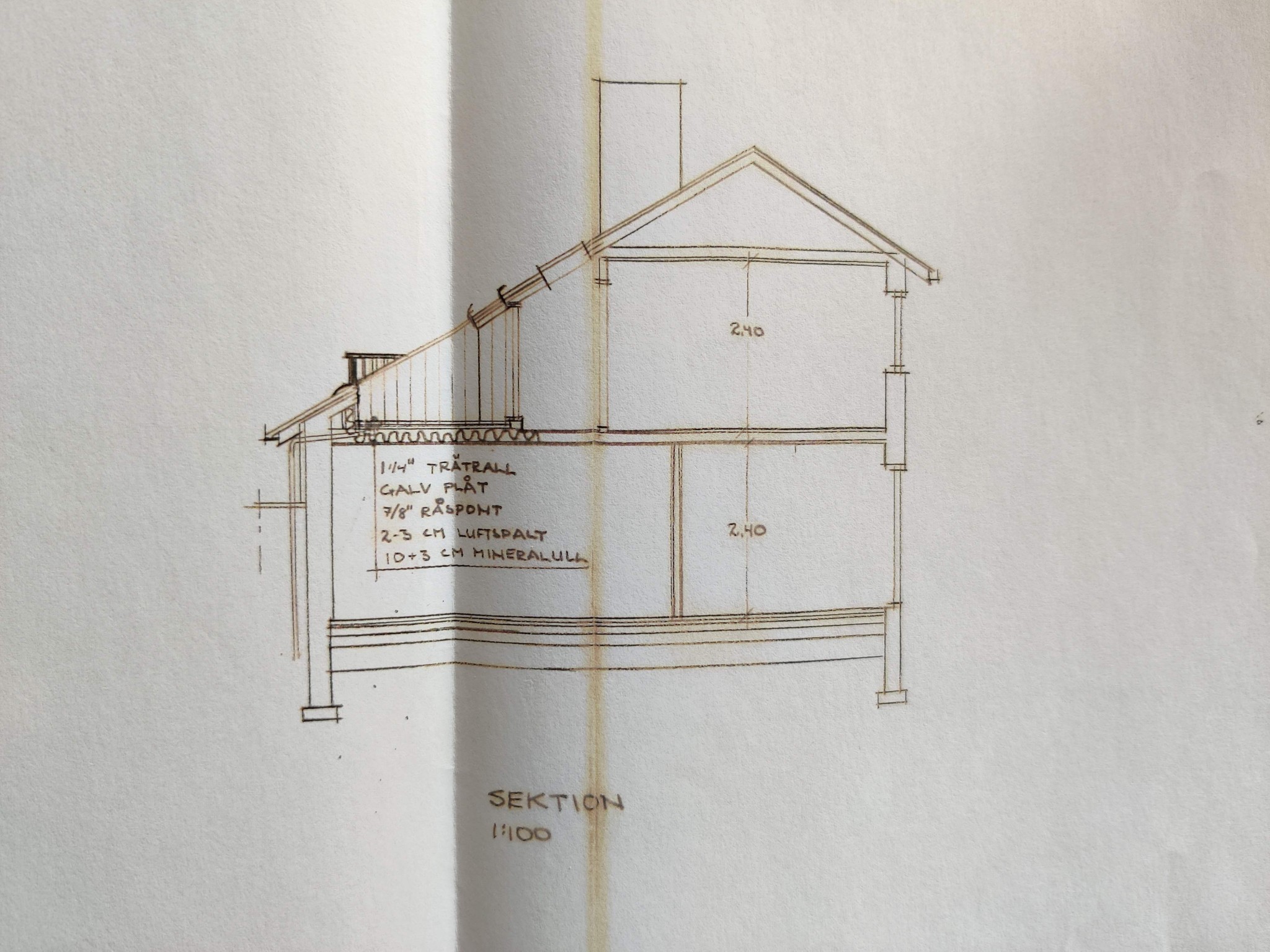
Spontaneously, I think there are two things that need to be checked and that are not clear from the section. 1) How are the beams in the floor structure between the floors spliced, if they are spliced (which I believe they are)? If they are spliced over the existing wall, it's not ideal to move it. 2) Is there anything in or under the bottom floor structure that can take up the column loads (independent of location) that result from an offset? The construction of the bottom floor structure is only hinted at. In the best case, there is a K-drawing.
I think they are spliced too, the ones over the boiler room are spliced and quite a lot.
But it should be possible to reinforce them further? Aesthetically, it would look best to align the beam with that wall
Regarding the foundation joists, it is a smooth fabric. The floor in the living room is currently raised, and in connection to it becoming a kitchen, a new one would be cast there with underfloor heating instead, so it can be adjusted according to loads .
I wish I had drawings of the joists, but I don't think there are good tips on how to get a feel for it without taking down the entire ceiling? How likely is it that the same splicing is continuous throughout? Because parts of the ceiling are taken down in the boiler room and the room inside the kitchen currently
If it's a house from the 60s, you can probably assume that the intermediate floor is built with a certain system. I don't think there are any drawings for this. Possibly for the ground floor. Can't you use a regular stud finder and draw in the position of the beams on a drawing? If you measure in the rooms on the upper floor on both sides of the heart wall, you should be able to get a good picture.
You see, Justus, this is exactly why you were tagged.
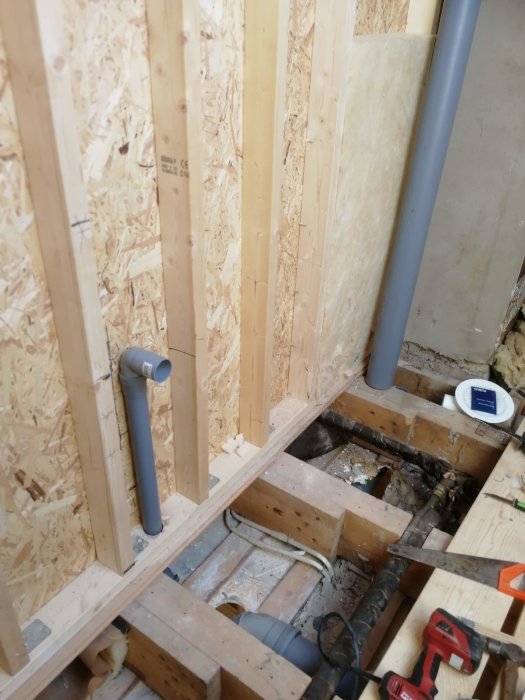
Now the brain kicked in and you're absolutely right, placing a beam there in a relatively simple way doesn't work well. I realized that the joint should be visible from above in the pictures when I was renovating the bathroom, and sure enough, it did.
You can clearly see where the joint ends. The wall visible there is between the utility room and the living room.
Looking at the ceiling in the utility room, the joint goes about 90 cm into that room. In short, the entire wall is load-bearing You learn something new every day.
Solution to achieve the aesthetics? Or is it easier to just come to terms with the fact that the beam, in that case, ends up where it ends up?
Yes. At least I don't look at the ceiling all the time (there could be other reasons too...).
Well then! I'm of the opinion that function comes before appearance in many aspects, but in this case, it will become a saga... When/if we do this, a stove was also considered like the picture I posted, so the chimney was intended to be built right next to the "load-bearing" wall on the upper floor to make as little impact as possible on the bedrooms, but then it falls apart
Oh well, time will tell! The partner changes her mind constantly about whether she wants to stay or not
It is difficult to formulate rules that hold in wet and dry. I also think that function is usually the most important. I do not hesitate to move a door or a window a few decimeters to get better light flow or furniture arrangement.
It's difficult to formulate rules that hold in wet and dry conditions. I also think that function is usually the most important. I don't hesitate to move a door or a window a few decimeters to get better light flow or furniture arrangement.
What kind of beam might be needed? The opening would be about 340 cm wide, so I assume a hea is preferable to keep the construction height down?
There will be some roof loads that need to be managed and calculated, but the beam dimension is approximately HEA 160 or glulam 90x315. Not too extreme.
There will be some roof loads that need to be managed and calculated, but the beam dimension is in the order of HEA 160 or glulam 90x315. Not too violent.
When you say roof loads, do you mean just the roof and not the intermediate floor?
If I then say that the wall does not support the roof at all, how do you react then?
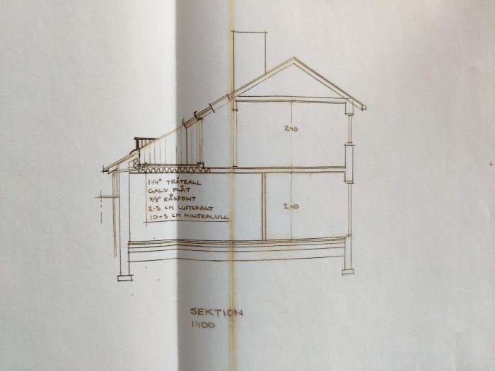
Then I say that you are wrong. The section clearly shows how a wall on the upper floor landing on the intermediate floor functions as a support leg for the roof truss.
Then I say that you are wrong. The section clearly shows how a wall on the upper floor landing on the intermediate floor acts as a support for the roof truss.
And you know what? You're right about that. I've now been up in the attic space and measured, and I am now trying to draft a floor plan that is as close to reality as possible based on what I've seen.
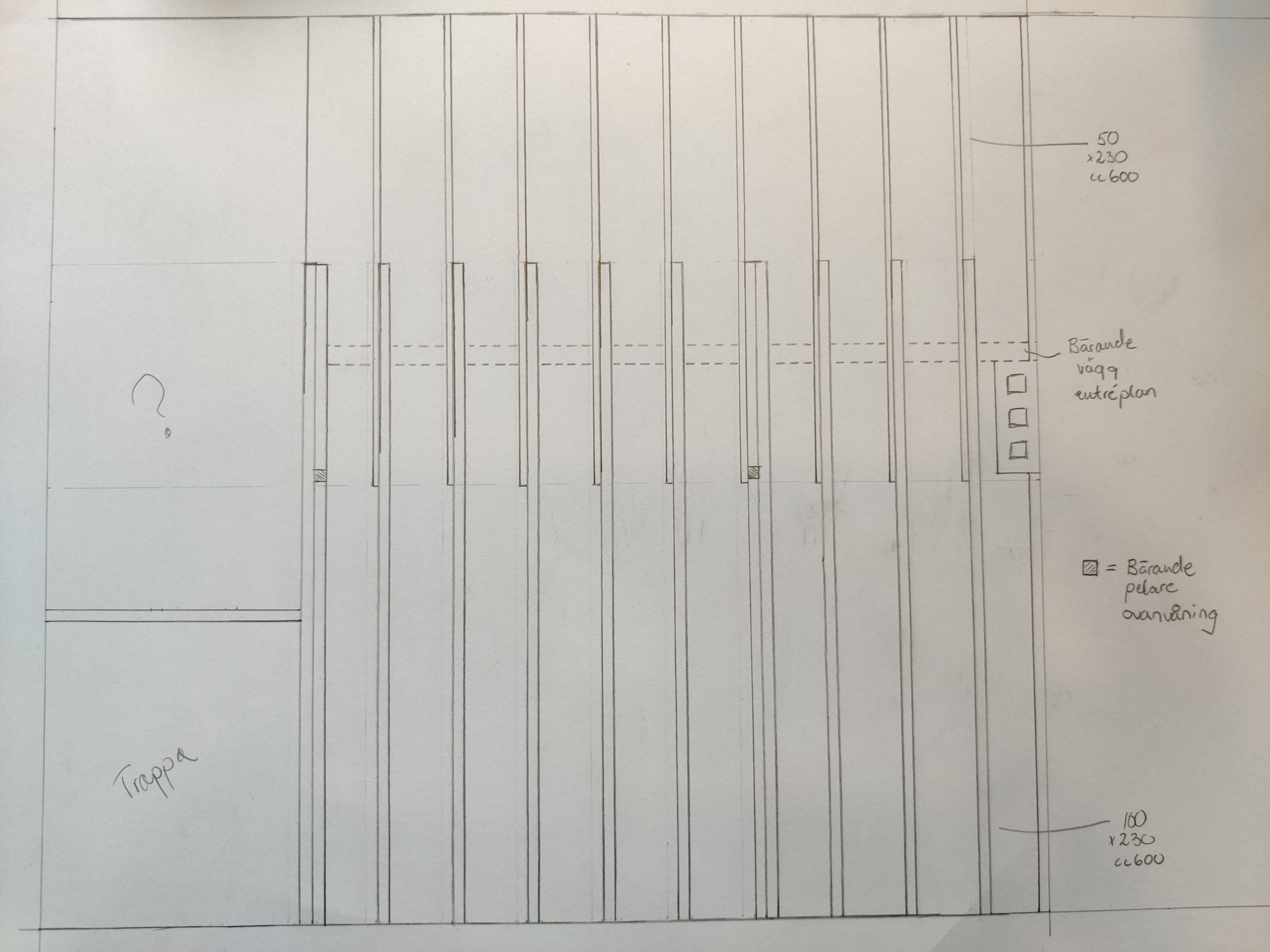
However, regarding the load-bearing part, it's actually a bit tricky because there is no load-bearing wall on the upper floor. Instead, there are 2 load-bearing columns since there are only 2 roof trusses on the house... quite a unique construction! But I was mistaken in my previous statement after seeing the floor structure; it's still the one taking the loads (good for me!).
I'll post my sketch/drawing here as soon as it's finished


")