41,966 views ·
360 replies
42k views
360 replies
Load-bearing capacity of aluminum L-beam
Sorry, but now guests are starting to arrive for dinner. Will continue tomorrow.
")
That's because you need to increase the mass on the top and bottom of the beam to counteract the deflection, not on the sides..Huggedugge1 said:
(Sounds crazy, I know, but that's how it is)
It may sound as strange as it wants. But that's how it is if you calculate with steel and most other metallic materials.
Then, of course, there must be something that holds the top and bottom together (like a web in an I-beam or the sides of a tube), but the further from the center of the cross-section (in the load direction) you can increase the area of the cross-section, the better...
Then, of course, there must be something that holds the top and bottom together (like a web in an I-beam or the sides of a tube), but the further from the center of the cross-section (in the load direction) you can increase the area of the cross-section, the better...
An interesting and challenging problem at least for those of us who do not live with it and need to solve it. I have read through the thread but may have missed the answer to the obvious question. How much does the midpoint need to be raised for it to work, i.e., how much must the deflection be reduced?
It's really quite intuitive that you should have a lot of material with a large lever arm to the neutral plane. It's not about the material but applies to all materials.Violina said:
May sound as strange as it wants. But that's how it is anyway when you calculate with steel and most other metallic materials...
Then, of course, there must be something that holds the top and bottom together (like a web in an I-beam or the sides of a tube) but the further from the center of the cross-section (in the load direction) you can increase the area of the cross-section, the better...
Since I don't work with many materials other than metals, I don't want to comment on it either.Bernieberg said:
But yes, I agree that I also (intuitively) think it should apply to "all other" materials as well, but since I'm not sure that is the case, I won't say anything about it.
Then I don't know what you mean by "lever arm to the neutral axis" because it's based on the cross-section that you calculate the resistance to deflection and the force has no lever arm with this type of load..
If it were a matter of twisting then yes, but not when calculating deflection.
The neutral plane is the plane where there is neither tension nor compression. This plane lies in the centroid of the cross-section during pure bending.Since I don't work with many other materials than metals, I don't want to comment on them either.
But yes, I agree that I also (intuitively) think it should apply to "all other" materials as well, but since I'm not sure if that's the case, I won't say anything about it.
Also, I don't know what you mean by "lever arm to the neutral plane" because it's from the cross-section that you calculate resistance to deflection and the force has no lever arm in this type of load.
If it had been about twisting, then yes, but not when calculating deflection.

Well… now you have REALLY lost me!!!
Self-supporting sheet metal is probably a good way to go, I think. I found a Plannja variant that didn't add much height. Then my idea is to lay the decking and screw it into the self-supporting sheet. (I haven't checked which screws etc, but I'll figure it out.)
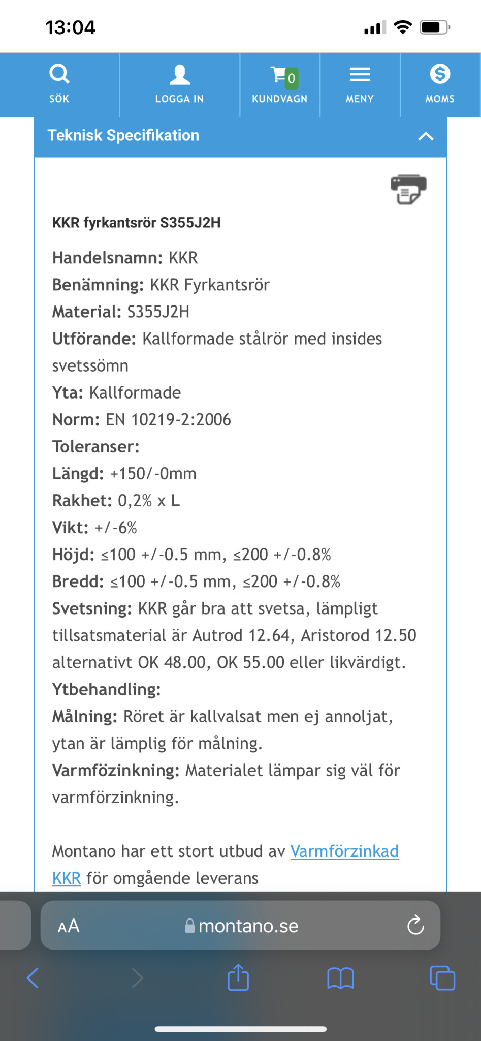
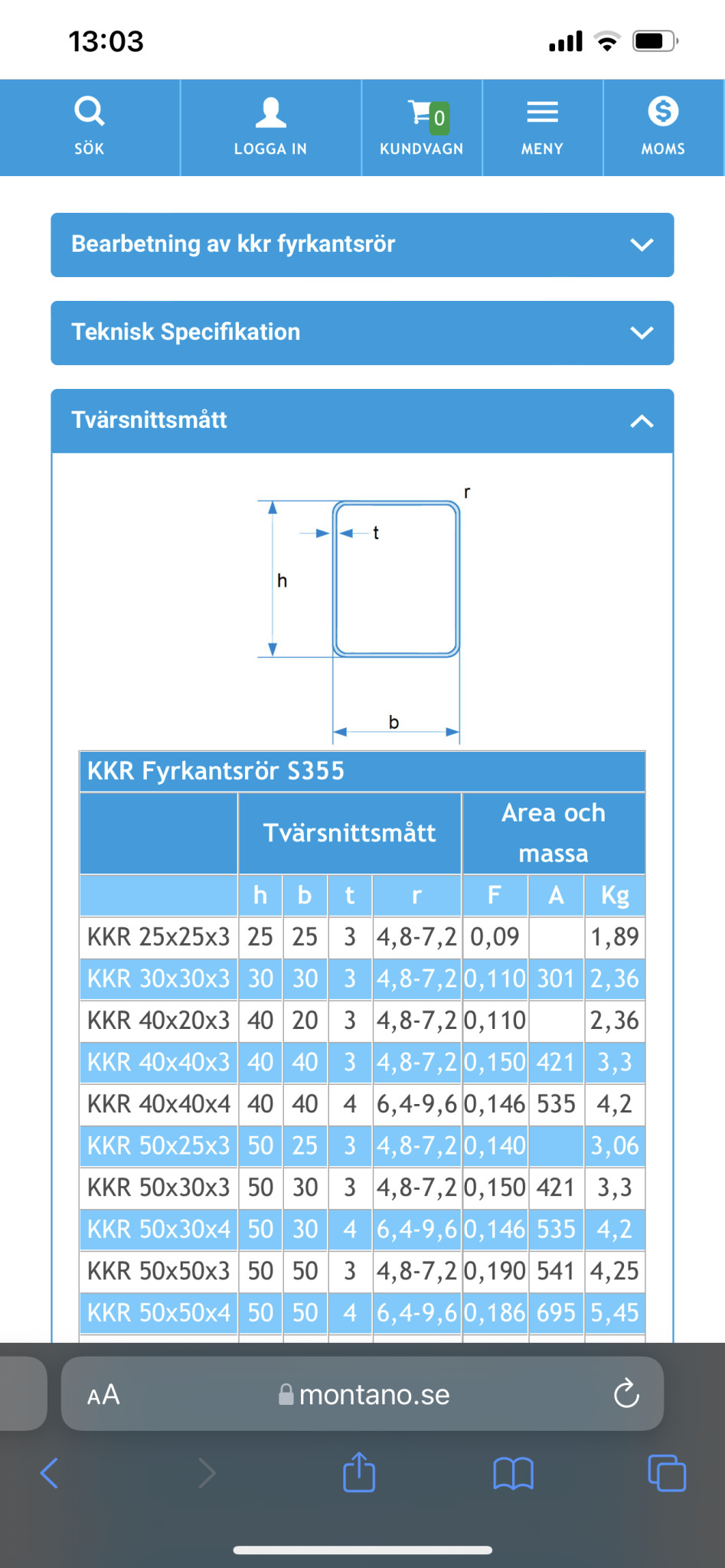
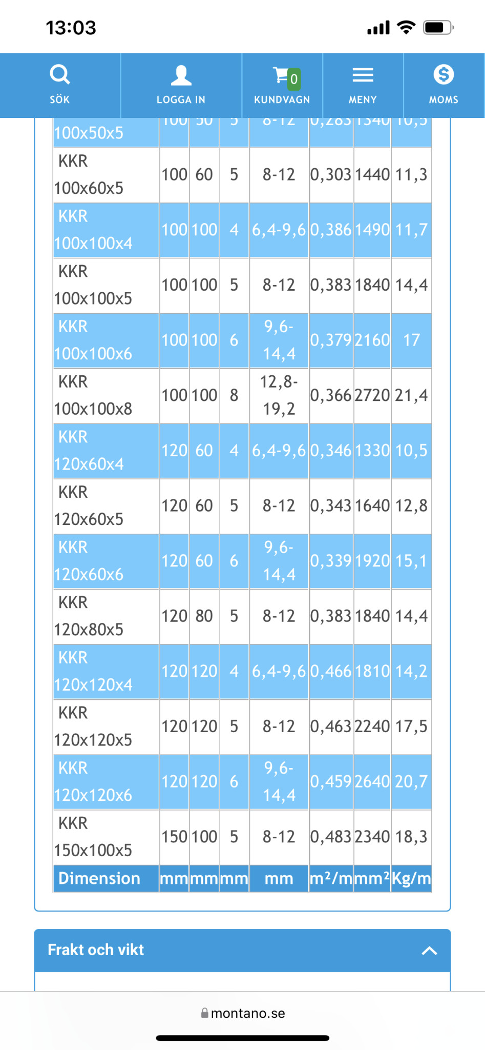
When it comes to the frame, I've looked at Montano.se and found KKR tubes. I was thinking of VKR or KKR square tubes. Since VKR is insanely expensive, I'm more interested in KKR, which should be rust-protected and then painted black or clad with wood. I was thinking of KKR 120*60 with 5 mm thickness. 840 cm + 420 cm will be the frame. The weight of the frame will then be approximately 320 kg.
The self-supporting sheet from Plannja is 7 cm in height and has a span of 480 cm. Then the covering width is 750 cm (unsure what happens when it has to cover 840 cm…) The weight of the entire roof sheet will then be about 100 kg depending on thickness. The decking weighs approximately 1000 kg, the frame 320 kg. So 1.5 tons in total.
So my question is... Is KKR 120*60 with 5 mm thickness a reasonable solution as a frame that will work? How much will the open part that goes over the pool sag when it closes???
Or can someone suggest something else suitable to make it work?
Can someone help me…
Self-supporting sheet metal is probably a good way to go, I think. I found a Plannja variant that didn't add much height. Then my idea is to lay the decking and screw it into the self-supporting sheet. (I haven't checked which screws etc, but I'll figure it out.)
When it comes to the frame, I've looked at Montano.se and found KKR tubes. I was thinking of VKR or KKR square tubes. Since VKR is insanely expensive, I'm more interested in KKR, which should be rust-protected and then painted black or clad with wood. I was thinking of KKR 120*60 with 5 mm thickness. 840 cm + 420 cm will be the frame. The weight of the frame will then be approximately 320 kg.
The self-supporting sheet from Plannja is 7 cm in height and has a span of 480 cm. Then the covering width is 750 cm (unsure what happens when it has to cover 840 cm…) The weight of the entire roof sheet will then be about 100 kg depending on thickness. The decking weighs approximately 1000 kg, the frame 320 kg. So 1.5 tons in total.
So my question is... Is KKR 120*60 with 5 mm thickness a reasonable solution as a frame that will work? How much will the open part that goes over the pool sag when it closes???
Or can someone suggest something else suitable to make it work?
Can someone help me…