41,963 views ·
360 replies
42k views
360 replies
Load-bearing capacity of aluminum L-beam
E Erik Lindroos said:If I calculate correctly, the deflection due to the weight of the sheet metal is about 5 mm over 8.4 m span (TP200). Quite independent of sheet thickness. Then you have to add decking, insulation, and snow, and a thicker sheet metal is better.
In comparison to the figures provided earlier for the stainless steel square "tube" with a 6700000 mm^4 moment of inertia:
A sheet, 1 mm thick, 854 mm wide: moment of inertia 8100000 mm^4
Sheet thickness 1.5 mm: 12000000 mm^4.
A sheet is thus stiffer than the tube, and you will distribute the load (whatever it may be in total) across five sheets.
Could one use a stainless Rectangular beam with dimensions 12 cm + 5 cm all around. That is, remove the wooden frame. ???E Erik Lindroos said:If I calculate correctly, the deflection due to the weight of the sheet metal is about 5 mm over 8.4 m span (TP200). Quite independent of sheet thickness. Then you have to add decking, insulation, and snow, and a thicker sheet metal is better.
In comparison to the figures provided earlier for the stainless steel square "tube" with a 6700000 mm^4 moment of inertia:
A sheet, 1 mm thick, 854 mm wide: moment of inertia 8100000 mm^4
Sheet thickness 1.5 mm: 12000000 mm^4.
A sheet is thus stiffer than the tube, and you will distribute the load (whatever it may be in total) across five sheets.
Now I understand! Please continue to "nag." I don't think that solution would work as I would have quite large wheels around the pool deck both when it is open and closed.O o5kar said:I'm not going to nag anymore, but your current wheels are attached to the bridge itself that moves, right? My suggested wheel would be fixed to the ground. My sloped rail achieves the same effect as your planned bump on the ground rail, but doesn't interfere with the rest of the function. -but I might have misunderstood the problem...
Or I still don't get it.
Well then, I just sympathize with you for spending 40k on pier reinforcement, since it might as well be hanging down until it needs to go over the edge of the pool  !
!
I was thinking of 1 wheel in the middle, but you might need several, so start with one, why don't you.
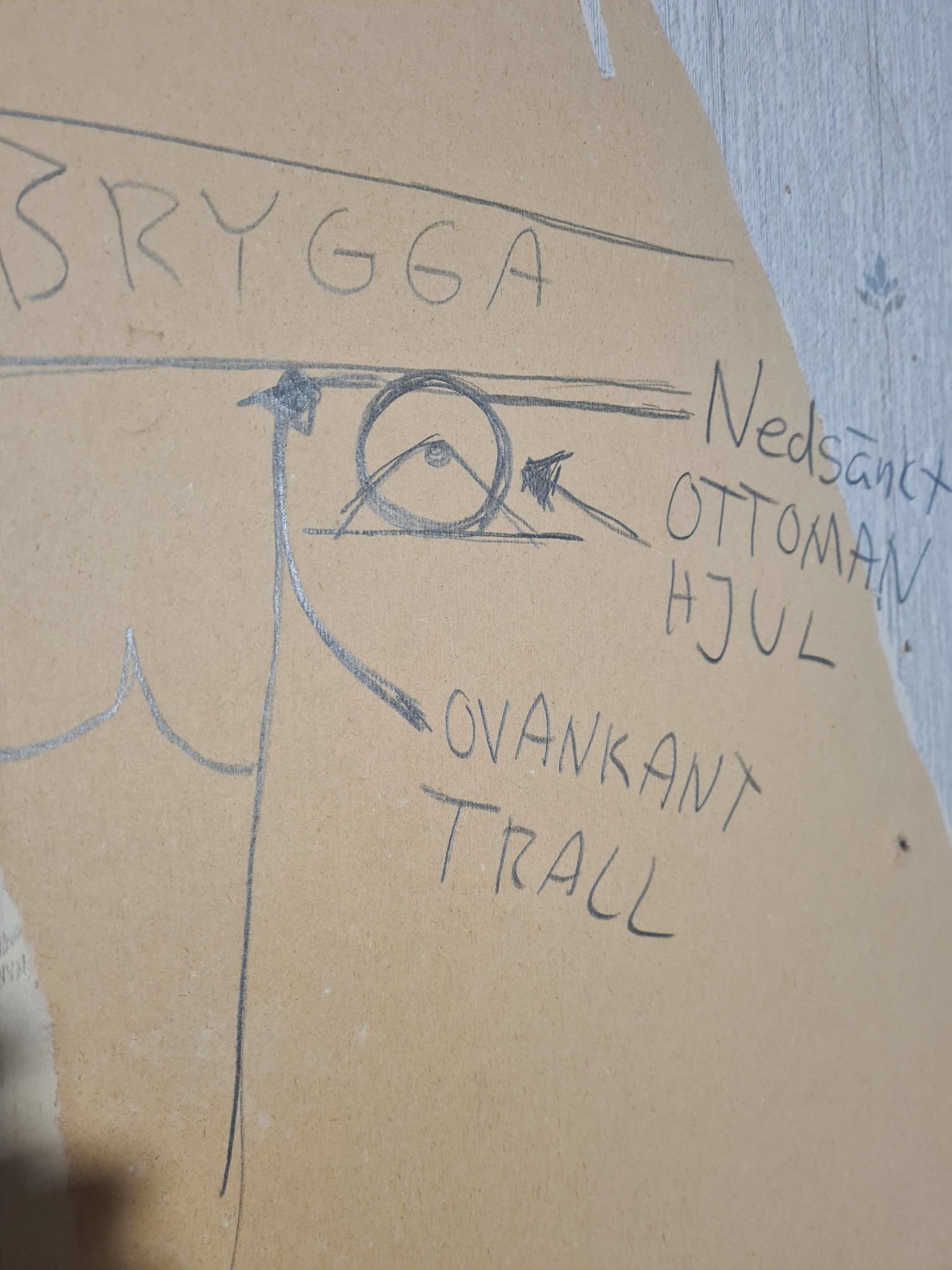
Look for something like Ottoman-wheels for industry that can handle a lot of weight. They can preferably be a bit larger so the rolling function doesn't mess up, so you lower them into the boards. As long as the wheels are firmly attached, and the rails on the dock are firmly attached, it's enough if 10mm protrudes above the deck.
!I was thinking of 1 wheel in the middle, but you might need several, so start with one, why don't you.
Look for something like Ottoman-wheels for industry that can handle a lot of weight. They can preferably be a bit larger so the rolling function doesn't mess up, so you lower them into the boards. As long as the wheels are firmly attached, and the rails on the dock are firmly attached, it's enough if 10mm protrudes above the deck.
A completely new idea. Would then remove the rails from the deck. But at the same time, it probably won't help against the flex in the deck/frame, which is the big problem. The sheet metal must be attached to something.
Need to eliminate the sway in the middle of the deck as well as the long sides...
Need to eliminate the sway in the middle of the deck as well as the long sides...
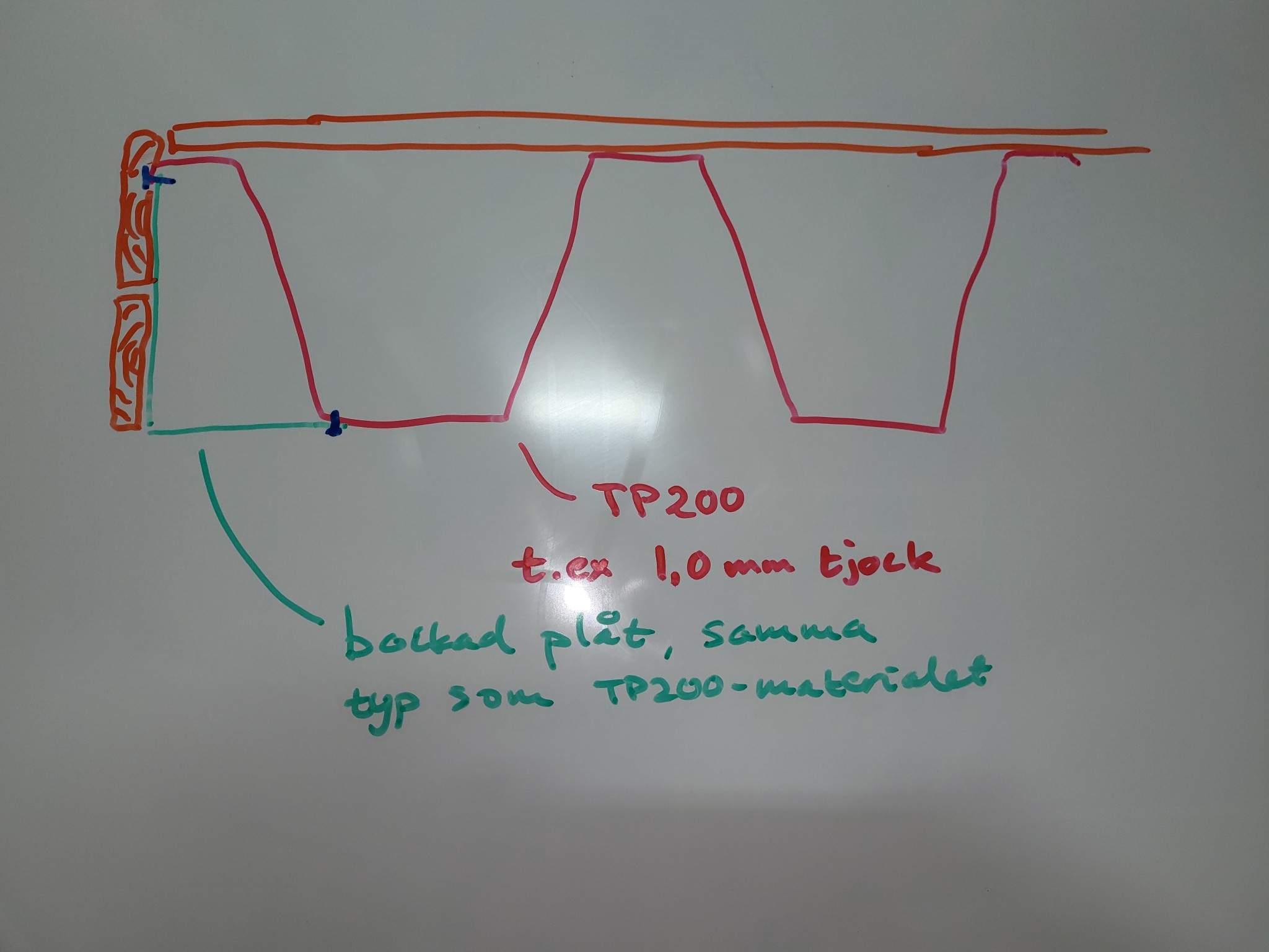
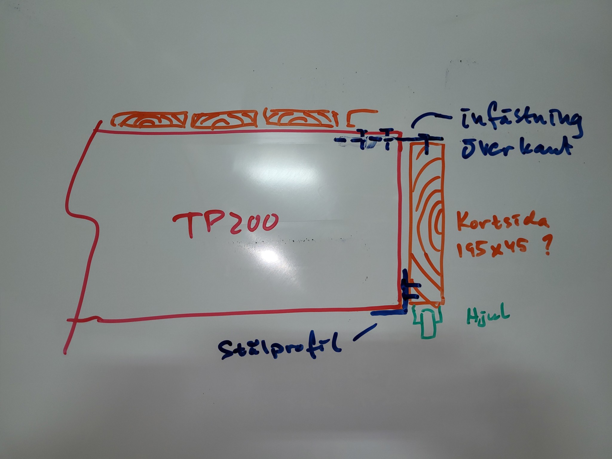
Well, this isn't super well thought out from my side. And I'm just a happy amateur. But I'm thinking that the sheet should basically take the entire load, so the edge doesn't need to be super strong (as long as you don't place a large point load there, for some unknown reason to me). The images illustrate how I would spontaneously imagine it.Huggedugge1 said:
The advantage of high-profile sheets is that they are made for long spans and outdoor use. They manage on their own. The disadvantage is that the adaptation to the surroundings can be a bit tricky. It concerns corrosion considering the pressure-treated wood and endings and fastenings that aren't like a regular roof.
So others are welcome to critique. The simplicity of the proposal with edge wheels should not be underestimated as long as the rest of the construction holds.
Need to think. Must know which frame I should use.
I probably explain as poorly as a rake, but the new recessed wheels are only meant to complement the existing solution. The sole purpose is to compensate for the sag at the end of the uncovering process when the bridge approaches the pool edge. This solves the wobble in the bridge, and if you also have wobble in the decking around the pool, you will need to fix support pillars to the ground under the recessed wheels.
To achieve the greatest possible load-bearing capacity on the beam, you want to have as much mass as possible as far away from the center of rotation as possible...
This can be achieved by taking a regular tube and welding additional material to the bottom and top...
And also pre-bending/over-arching/pre-stressing the beam in an upward arc...
All this is complicated by the fact that the construction is essentially already finished, but it's not impossible...
This can be achieved by taking a regular tube and welding additional material to the bottom and top...
And also pre-bending/over-arching/pre-stressing the beam in an upward arc...
All this is complicated by the fact that the construction is essentially already finished, but it's not impossible...
So there is no misunderstanding: is the problem that when the pool cover is partially open, the free long side hangs down so much that it becomes an issue when approaching the fully open position and the cover's long side needs to get back on the edge again?
When the cover is fully open or fully closed, it has support along all four sides and everything is fine?
When the cover is fully open or fully closed, it has support along all four sides and everything is fine?
Now it would probably be best if @Huggedugge1 responds, but if the cover comes over the edge on the far side but not on the mezzanine side, then I definitely don't understand how that works.Bernieberg said:
So there is no misunderstanding: is the problem that when the pool cover is partially open, the free long side hangs down so much that it becomes a problem when approaching the fully open position and the long side of the cover should go back onto the edge?
When the cover is fully open or fully closed, it has support along all four sides and everything is fine?
Have you already tried with an IPE 10 spanning 840 cm?HEA beam becomes too heavy.
IPE sways, we have found. Bought 2 pieces of 10 cm and had to box them in with corten steel and paint. Sways 3.5 cm...
Pipe is something someone has recommended.
U-beam...
Profile tube is what I'm hoping for now.
Truss is another suggestion but...
Regardless of the solution, the maximum height is 23.5 cm to avoid raising the "terrace" which currently has a 23.5 cm clearance.