Yes, that is my conclusion, i.e., that the trusses were there before the crawl space/rafters were added. It would be nice to have some form of formula/rule of thumb for the dimensioning of trusses as confirmation... I still have my book on mechanics of materials from Chalmers, but I studied mechanical engineering and not Civil Engineering.... maybe it's time to dig it out.
Actually, I don't think it's necessary to calculate it. The doubts I initially had regarding the construction of the trusses have disappeared with the latest pictures. (Still, it would be fun to see a picture of the truss support on the outer wall if possible) Even if the technical knowledge was lacking in the past, they were not stupid. Moreover, the quality of the timber was consistently higher than today. If you want to check, you can try Träguiden from Träinformation. As a comparison, the bending resistance for a 3x7 inch wooden beam is slightly greater than for a 45x195 mm beam. Furthermore, your c/c distance between the trusses is less than the normal 1200 mm.
Nice to come across a Chalmerist in exile! I myself was there from '67-'72 (approximately). I also checked the American cheat sheet. Fun but cumbersome. I worked one summer at an architectural office in the USA in 1969. The biggest drawback with foot and inch measurements is the scales. Instead of drawing at 1:100, you draw at 1 inch to 8 feet, i.e., ≈ 1:96!
Thank you, I will return with pictures of the layout after the weekend, but if my memory doesn't fail, they go straight through the wall. The walls are made of horizontal planks, 3 1/4", 80mm. They have used the scrap pieces for, among other things, walls on floor 2. I have been browsing through the wood guide but haven't found tables with bending resistance.
No, I do not agree with that conclusion justusandersson.
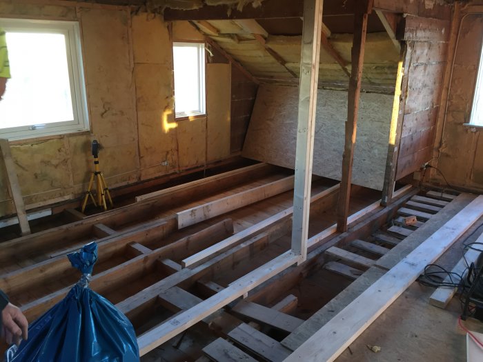
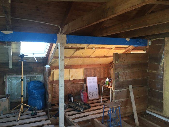
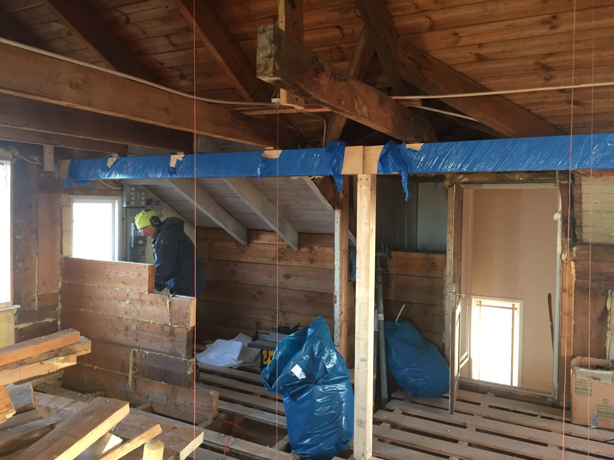
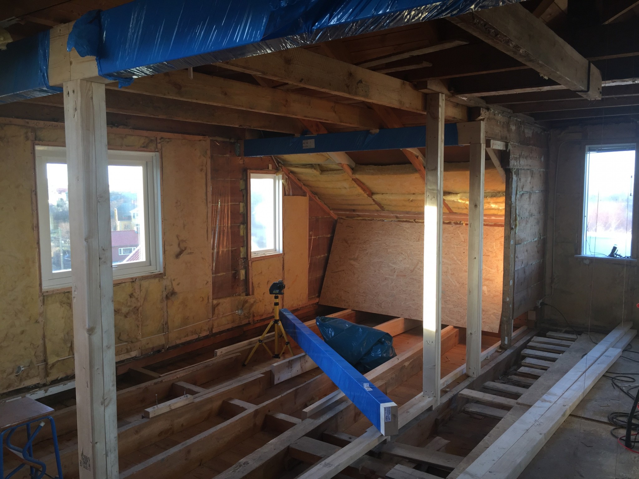
What I think I see are two supporting side joists that work together with A-trusses. A common construction at that time. The knee wall is not load-bearing for the reason you describe, but the joists are likely load-bearing.
By eyeballing it, a 3x7 inch lumber should hold as joists if the distance between transversal partitions is under 3 meters and the roof is made of sheet metal or another lightweight material... but since the joists and A-trusses work together and there are some unknown factors, this is just a rough guideline.
At least one of the ridges does not rest on the trusses. Possibly due to settling over the past 100 years, but in any case, the ridge rests on a pillar that "just" stands on a floor joist.
I will come back with detailed pictures after the weekend.
I have great respect for our Finland-Swedish friends' knowledge of old building techniques. One can easily be limited to the solutions one has seen oneself. However, I find it difficult to see how the "åsarna" could be load-bearing unless the house is very short. I haven't seen any information about the house's length, though. A common truss model is called the Swedish truss. There, the outer part of the high leg rests on slanted support legs that land on a beam lying on the attic floor beams. This truss is especially common with masonry exterior walls where you don't want to take the load directly on the masonry walls. However, this doesn't seem to be relevant in this case.
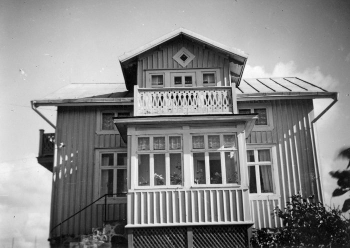
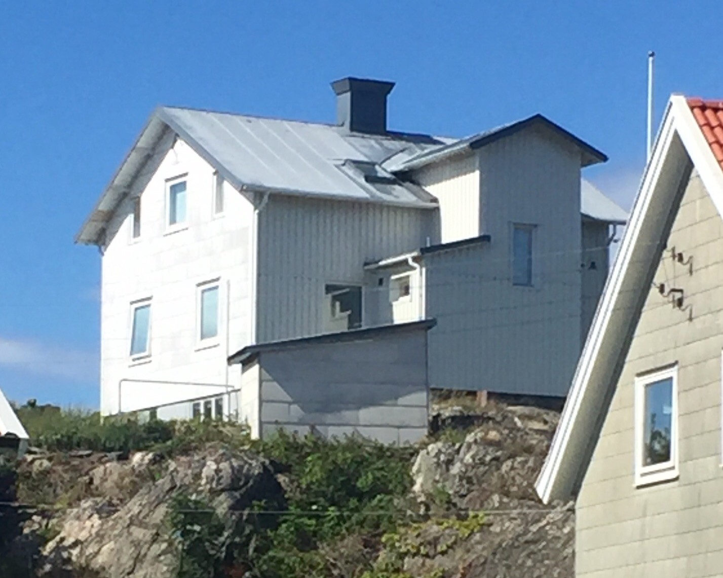
Is it in the "Kråkan"? Metal roofing is good because it is a relatively lightweight construction. With an 8 m length, the ridge beams cannot be load-bearing. The span is much too long for those dimensions.
It's on Styrsö in the Gothenburg archipelago (I actually live in or near Kråkan ). 8m is the total length, each ridge is about 2.5m on each side of the middle section.
I am attaching drawings (newly made) that might give a better insight. View attachment Planritning.pdf View attachment Fasadritning.pdf
") I still have my book on mechanics of materials from Chalmers, but I studied mechanical engineering and not Civil Engineering.... maybe it's time to dig it out.
I still have my book on mechanics of materials from Chalmers, but I studied mechanical engineering and not Civil Engineering.... maybe it's time to dig it out.