Hi, I'm playing around in an early stage by blowing out all the walls in a part of the house. I've looked into tables but can't find a guide that considers the interaction between constructions.
Suggestion according to picture:
Floor structure with a living area in the form of a bedroom.
Glulam beams 140x405x10000mm, CC 2000mm, free-spanning 10000mm. Glulam pillars 140x140x2800mm Floor structure 45x220x8000 CC 600mm, free-spanning 2000mm. C14? C24?
My suggestion has no basis in calculations, but only in rough amateur translation from tables.
I'm not seeking a complete calculation but just a hint for rough planning of any renovation, before the construction starts, a structural engineer will of course calculate and draw it up.
Of course, I would like to have only 2 sections instead of 4, but I don't want the total height of the floor structure to exceed 700mm. Maybe the solution is 140x630x10000 glulam, and 220's in between, but then you wouldn't get stiffness support from the 220's.
The 220's of the floor structure might not be full length, but rather spliced above the glulam, not a general splice. The top of the 220's is covered with chipboard that is screwed down. The bottom of the 220's is covered with slats and gypsum. I haven't thought about needing to reinforce or glue.
What do the pros think? (and the rest of you like me?)
Thus, the longest overhang of the three glulam beams in the middle is now approximately 8000mm.
Also adjusted the height of the outermost glulam beams to 630mm where the 220s connect to instead of on top, the overhang on these is unchanged at 10000mm.
Glued laminated timber typically has the same price per cubic meter regardless of its dimensions. Therefore, tall (and narrow) glulam beams offer the best performance in relation to cost. At the same time, glulam is about three times as expensive as regular construction lumber, so it's not an optimal replacement. In practice, it's the cost that determines the dimensions. If I try to translate your sketched alternative to reality, it requires 5 10-meter long glulam beams with dimensions 215x495, 17 8-meter long 45x145 C24, and 10 90x90 glulam columns for a calculated cost of 58586 kr. Here, I have calculated 10000 kr/cubic meter for glulam and 3500 kr/cubic meter for other timber. If we instead go with 4 glulam beams with dimensions 90x720, 17 45x195 C24 (which can be built down), and 8 glulam posts 90x90, the estimated cost is 32365 kr. A third option with 3 glulam beams 90x855, 9 glulam joists 42x315 (built down), and 6 glulam columns gives a cost of 34879 kr. Additionally, one would need stronger floorboards that can rest on c/c 1200 mm. I could create such a program that you're asking for in Excel, but hardly anyone other than me would be able to use it...
Glulam usually has the same price per cubic meter regardless of its dimensions. Therefore, tall (and narrow) glulam beams provide the best performance in relation to cost. At the same time, glulam is about three times as expensive as regular construction timber, so it's not an optimal replacement. In practice, it's the money that dimensions. If I try to translate your sketched alternative to reality, it requires 5 pieces of 10 meters long glulam beams with the dimension 215x495, 17 pieces of 8 meters long 45x145 C24 and 10 pieces of 90x90 glulam columns for a calculated cost of 58586 kr. I have calculated with 10000 kr/cubic meter for glulam and 3500 kr/cubic meter for other wood. If you instead go for 4 glulam beams with a dimension of 90x720, 17 pieces of 45x195 C24 (which can be built down), and 8 glulam posts 90x90, the calculated cost is 32365 kr. A third variant with 3 pieces of glulam beams 90x855, 9 pieces of glulam joists 42x315 (built down), and 6 pieces of glulam columns results in a cost of 34879 kr. You also need heavier floorboards that can rest on c/c 1200 mm. I could make such a program as you are asking for in Excel, but hardly anyone other than I would be able to use it...
Awesome! Now we're getting somewhere! That's fun
I have to start by saying that the reason for my late reply is that my Sketchup skills are not the best .
In any case, I redrew a bit after taking in your response and would love a couple of quick eyes on the picture, would be greatly appreciated!
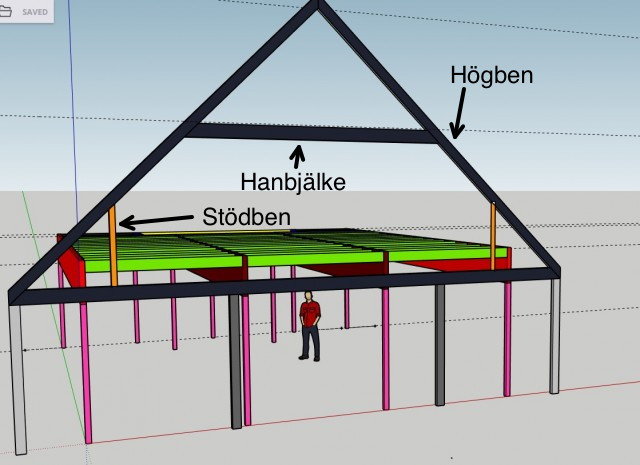
Image explanation:
Light red: Glulam 90x720x10000
Dark red: Glulam 90x720x8500
Pink: Glulam 90x90x approx. 2400
Light green: C24 45x195x2600 CC60
Dark green: C24 45x195x approx. 2000 CC60
Light blue: 3 nailed together C24 45x195x2600 alternatively glulam 180x180x2600
Dark blue: 3 nailed together C24 45x195x1500 alternatively glulam 180x180x1500
Yellow: Glulam 90x225x8000
Stair opening approx. 4300x1500
Columns placed so they do not block windows.
Attachment of glulam columns and glulam beams with large long flat/T iron.
Attachment of glulam columns and concrete floor with heavy angle irons.
Attachment of C24 195's and glulam beam with beam shoes.
Underside of 195's covered with grid and plaster, alternatively raw plank.
Beams visible. From floor to underside of beam approx. 2400mm, from floor to underside of 195's approx. 2900mm.
Topside of 195's covered with chipboard flooring that is screwed, preferably not glued.
The upper floor will be occupied by bedrooms.
Questions:
*How large permanent "braces" are needed for this construction not to collapse like a house of cards? I would prefer as few as possible since I have many door openings and windows.
*How long can flat/T irons be needed? 50x10x2000mm?
*Anything else I should consider before passing this on to a constructor?
Is any part attached to an existing wall or is the whole construction free-standing?
Isn't there one too many zeros in the last measurement?
According to the image:
Light gray: Outer wall built in 45x220x2400 CC60
Dark gray: Load-bearing inner wall built in 45x220x2400 CC60
Black: Roof truss framework built in 45x220 CC1200
Orange: Lean-to braces built in 45x90 CC60
The idea is to saw off and attach the existing truss supports to the new glulam beams.
And install new lean-to braces above the glulam into the truss.
And "move up" the truss capping so you still have okay ceiling height on the upper floor.
Between the four glulam pillars on the gable closest as per image, large windows are planned.
On both long sides, there are existing door openings, as well as a 4000mm opening.
On the opposite gable, I have existing two windows and an entry door.
The dark gray existing load-bearing inner walls are to be completely demolished.
The reason for the overly ambitious flat/T-beams is precisely to counteract tipping, a bit like a table, which generally doesn't require any braces.
All glulam pillars (except the two that are placed 1500mm in from the far gable wall) are placed inside the existing inner walls, the idea is to then frame in existing walls 90mm and fill with insulation, where there will be no windows.
A lot of text, but I hope I've made it understandable.
I have an intended budget of around 100,000 SEK for the material itself according to my SketchUp drawings. Then covering materials + labor are additional.
So the question remains, how many braces do I need to incorporate? I have no experience at all with building techniques regarding lateral forces, etc.
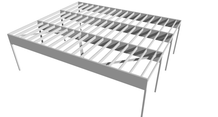
If one short side is attached to the house's shell and this is stabilized in the usual way with sheet material etc., it is sufficient with diagonals in the plane of the floor structure, e.g., on the underside of the green beams. The correct naming of different roof truss details facilitates communication.
If one short side is attached to the house's shell and this is stabilized in the usual way with panel material, etc., it is enough with diagonals in the plane of the joists, e.g., on the underside of the green beams. Correct naming of different roof truss details facilitates communication. [image]
What do we mean by diagonals in the plane of the joists? Horizontal or vertical diagonals?
I am, by definition, going to weaken a gable, the idea is to stabilize with braces essentially everywhere there are no windows or doors.
My SketchUp skills are not the best, but I think you can see what I'm trying to show.
If we entertain the thought of building this as if it were freestanding, what would be the approach then for stabilization?
I have an illustration to show the principle of what I mean with diagonals in the plane of the floor structure. If one short side of the construction is attached to the building's shell, that type of diagonals may suffice. If the construction is completely freestanding, each plane (i.e., side and floor structure) needs to be stabilized with diagonals.
Click here to reply
Vi vill skicka notiser för ämnen du bevakar och händelser som berör dig.