Bosse: My calculation of the distributed load I unfortunately don't have anymore, just the total, 18 kN/m. Out of that, 12 kN/m should be snow. Then the IPE 270 bends down about 16 mm. It was on the 19/11 that I did the calculation, but I can't verify it. However, I usually don't calculate on the low side. It's a very large roof...
Bosse: I unfortunately no longer have my calculation of the distributed load, only the sum, 18 kN/m. Of that, 12 kN/m should be snow. Then the IPE 270 bends down about 16 mm. I made the calculation on 19/11, but I can't verify it now. However, I usually don't underestimate. It's a very large roof...
What influence width did you use then? I get 6.9kN/m for characteristic snow load
I really don't remember how I thought other than that I remember thinking there were unusually large overhangs at the exterior walls. But, I must have made a calculation error, because when I now recalculate it from scratch, I get 6.88 kN/m for characteristic snow load, i.e. the same as you. Then 18 kN/m is obviously unreasonable. It should instead be 11.2 kN/m for snow load and self-weight. I usually use the computer's own calculator. It can mess things up if you forget to first press Clear and then Clear All. I am an old man.
Justus, no shadow shall fall on you or your calculations. I'm just glad that the beam might potentially be downsized
As I said, I am extremely grateful for all the input....
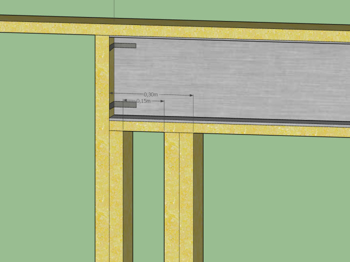
What do you think about this support?
The beam is attached with French screws downwards and possibly upwards. The cap rail and bottom rail are also glued.
I’m thinking of 4 French screws downwards in each support and 4 French screws upwards in each support. In the next "layer" I can also place a stud vertically straight across the beam from each side. The stud is attached to the cap rail, the bottom rail, and further down in the structure.
I really don't remember how I thought except that I remember thinking there were unusually large overhangs at the exterior walls. But, I must have made a calculation error, because now when I recalculate it from scratch, I get 6.88 kN/m for characteristic snow load, i.e., the same as you. Then 18 kN/m is obviously unreasonable. It should instead be 11.2 kN/m for snow load and self-weight. I usually use the computer's own calculator. It can make a joke of it if you forget to first press Clear and then Clear All. I'm an old man.
It's really easy to happen, it's happened to all of us
Justus, no shadow should fall on you or your calculations. I'm just glad the beam might eventually be scaled down
As mentioned, I'm extremely grateful for all the input....
What do you think about this support?
The beam is fastened with a lag screw downward and possibly upward. The top rail and bottom rail are also glued.
I'm thinking of 4 lag screws downwards in each support and 4 lag screws upwards at each support. In the next "layer," I can also draw a brace vertically straight across the beam from each side. That brace is fastened both to the top rail, the bottom rail, and further down in the structure.
[image]
Place the double posts at the end of the beam instead so that the support does not become too "long," as it may cause restraining forces if the support is too extensive. One screw on each side at the bottom of the beam is sufficient. If you screw at the top, restraining forces will also occur. So try to allow the beam to move freely parallel to its longitudinal axis.
The angle brackets you have drawn should be screwed only into the wooden rail and pressed against the beam. This prevents the beam from moving laterally but allows it to move longitudinally.
Then the beam must be braced laterally along its entire length. You could screw upwards through the flange, but then the hole in the steel should be elongated in the beam's lengthwise direction. Ideally, the top flange should be braced laterally directly to the roof beams.
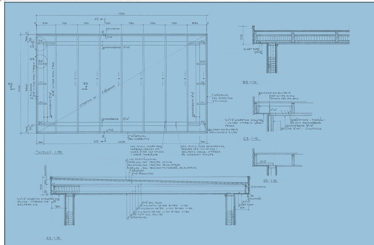
Difficult to explain, so I attach a picture of how I did it at home. It became very messy, so we'll see how explanatory it turned out
The point of bossespecial's sketch is that it shows how you can brace the beam both against tipping and lateral displacement without preventing its movement lengthwise. Steel, as we know, has significantly greater longitudinal expansion than wood.
What do you mean by the roof drawing? That's a different house.
Damn, how depressing, I'm realizing now that I don't have any construction drawing for the big house. I wonder how the engineer will be able to make the calculation then.