
4,255 views ·
6 replies
4k views
6 replies
Bearing of beam on slender post/brick wall

I have an 8"*8" beam that I plan to use as a support for a wall. On one end, I have (planned to have) a 95*95 post, on the other end, a brick wall that runs parallel to the beam. The width is one brick thick, approximately 120mm.
My concern is that the beam is significantly wider than the supports; on the wall, the beam will be about 40 mm wider than the wall on each side.
On the post, it’s about 50 mm wider.
I'm considering whether to notch the beam for the post and the wall to get the most stable support possible and avoid the beam tipping over on the support (which should be less likely anyway), or if there's another way to do it.
I’d prefer not to increase the dimension of the post, as I want as little of the post visible as possible; a large part of it will disappear when I level up the uneven wall.
Suggestions and tips are welcome.
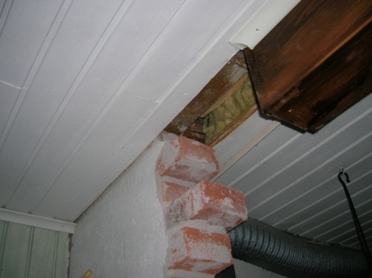
(ps. it’s not the beam in the picture that this text is about)
This is what the support on the wall looks like:
My concern is that the beam is significantly wider than the supports; on the wall, the beam will be about 40 mm wider than the wall on each side.
On the post, it’s about 50 mm wider.
I'm considering whether to notch the beam for the post and the wall to get the most stable support possible and avoid the beam tipping over on the support (which should be less likely anyway), or if there's another way to do it.
I’d prefer not to increase the dimension of the post, as I want as little of the post visible as possible; a large part of it will disappear when I level up the uneven wall.
Suggestions and tips are welcome.
(ps. it’s not the beam in the picture that this text is about
)This is what the support on the wall looks like:

You should not remove the beam as it weakens the end of it. You can widen the supports by placing a stud across under the beam. Wood has different bearing capacities depending on the direction of the load. I had a similar problem with a glulam beam, but in that case, manufacturers have simpler calculation programs that you can use.
Thank you for that! But what is the difference between placing a joist across the support, versus placing the beam directly on it? Wouldn't it be the same load on the joist as it is on the beam without the joist?
Or is it about placing a joist where the fiber direction is across the support=more durable?
Is a support that is 45mm deep enough if the beam is about 380 cm long?
I wonder if it's possible to make a support on the log wall with a horizontal joist of the same width as the beam, and support it with one or two 45*95 that stand on the floor structure and are screwed into the log wall.
Could that be sufficient to take up the loads?
Or is it about placing a joist where the fiber direction is across the support=more durable?
Is a support that is 45mm deep enough if the beam is about 380 cm long?
I wonder if it's possible to make a support on the log wall with a horizontal joist of the same width as the beam, and support it with one or two 45*95 that stand on the floor structure and are screwed into the log wall.
Could that be sufficient to take up the loads?
Without knowing how large the support reactions (compressive loads) are in the supports, it's not possible to answer your last question. That is, how large the line load resting on the beam divided by two (2).
You also need to consider at the post that the pressure is absorbed parallel to the fibers in it (which is perfectly fine) but perpendicular to the fibers in the beam (which is less favorable from a strength perspective).
At the brick wall, you need to consider that the angle change (due to deflection in the beam) creates a crushing effect in the wood where the wall ends/the support begins. Therefore, it's better to either place a piece of harder rubber (car tire) between the beam and the brick wall (best), or insert mortar under the beam up to five centimeters to allow room for such an angle change.
As guidance for the beam/post, you can use a piece of M16 threaded rod that you drill down the middle of the post and let it go up five centimeters into the beam. It does not reduce strength.
As guidance for beam/brick wall, you can embed a couple of pieces fi ten rebar into the joints so that they go 10 cm into the beam. These do not reduce strength either.
An 8"x8" beam will not topple. But if it is homogeneous (taken whole from a tree), you should expect that it may twist and over time also crack radially, viewed from the cross-section. Therefore, it's better to use 2 pieces of 4"x8" that are glue-laminated (the heart side should be outward on both logs) and screwed together. This way, the wood's 'inherent' forces counteract each other so that the beam remains straight and a heart side does not crack as easily as a sapwood side.
_________________
Byggaren
You also need to consider at the post that the pressure is absorbed parallel to the fibers in it (which is perfectly fine) but perpendicular to the fibers in the beam (which is less favorable from a strength perspective).
At the brick wall, you need to consider that the angle change (due to deflection in the beam) creates a crushing effect in the wood where the wall ends/the support begins. Therefore, it's better to either place a piece of harder rubber (car tire) between the beam and the brick wall (best), or insert mortar under the beam up to five centimeters to allow room for such an angle change.
As guidance for the beam/post, you can use a piece of M16 threaded rod that you drill down the middle of the post and let it go up five centimeters into the beam. It does not reduce strength.
As guidance for beam/brick wall, you can embed a couple of pieces fi ten rebar into the joints so that they go 10 cm into the beam. These do not reduce strength either.
An 8"x8" beam will not topple. But if it is homogeneous (taken whole from a tree), you should expect that it may twist and over time also crack radially, viewed from the cross-section. Therefore, it's better to use 2 pieces of 4"x8" that are glue-laminated (the heart side should be outward on both logs) and screwed together. This way, the wood's 'inherent' forces counteract each other so that the beam remains straight and a heart side does not crack as easily as a sapwood side.
_________________
Byggaren
Oh, oh that was a lot there . I’ll dive into it for a few hours. Thanks a lot, I’ll probably have some questions about it.
The beam is probably at least 100 years old, so I think it has twisted and cracked enough. Currently, I have two screwed and glued 45*195 beams spanning 230 cm at this spot, but I want to avoid having a pillar in the middle of the floor and get a more suitable beam, as the house is over 100 years old as well.
. I’ll dive into it for a few hours. Thanks a lot, I’ll probably have some questions about it.The beam is probably at least 100 years old, so I think it has twisted and cracked enough. Currently, I have two screwed and glued 45*195 beams spanning 230 cm at this spot, but I want to avoid having a pillar in the middle of the floor and get a more suitable beam, as the house is over 100 years old as well.
Just wanted to inform you that an 8"x8" beam has a Wx (bending resistance) of 1333 cm3 while a beam made of two glued 45x195s has a Wx of 570 cm3. 'Eight by eight' could theoretically carry almost 3 times as much as the beam you currently have, but that's not accurate. You have to take into account the cracks in the 'eight by eight', which reduces the effective cross-section considerably, and thus lowers the Wx. If the wood quality in the 'eight by eight' is poorer than that of the current 2x4.5x19.5 beam, it also negatively impacts the load-bearing capacity. A whole log is typically classified in the lowest strength class because the knots in the wood can grow all the way to the core, which cannot be seen in a whole log. Hence, the lowest strength class. However, one can clearly see in a sawn 45x195 whether there are continuous knots (weakening) or just a knot on the edge (also weakens the strength but differently depending on where and how the knot is situated) or if it is knot-free (highest strength class).
At the same time, you're increasing the span from 2.3 m to 3.8 m, which increases the moment (deflection) significantly more than the Wx increase from the dimension change. Calculated with the lowest strength class in both cases, it results in an increase of Mmax (maximum moment) by no less than 42% if q/m (load per meter of beam) is the same in both. It likely isn't since a 3.8 m long beam is loaded more from the overlying part than a 2.3-meter one. Double the load is more likely, which would even out with the increased Wx even taking crack formation in the 'eight by eight' into account. But... no consideration has been given to the long-term deformation (permanent deflection) Ymax. It must not exceed 1/400th of the span, i.e., 9.5 mm in the middle at a 3.8 m span. I would therefore think that Ymax will be the dimensioning factor in your case.
_________________
Byggaren
At the same time, you're increasing the span from 2.3 m to 3.8 m, which increases the moment (deflection) significantly more than the Wx increase from the dimension change. Calculated with the lowest strength class in both cases, it results in an increase of Mmax (maximum moment) by no less than 42% if q/m (load per meter of beam) is the same in both. It likely isn't since a 3.8 m long beam is loaded more from the overlying part than a 2.3-meter one. Double the load is more likely, which would even out with the increased Wx even taking crack formation in the 'eight by eight' into account. But... no consideration has been given to the long-term deformation (permanent deflection) Ymax. It must not exceed 1/400th of the span, i.e., 9.5 mm in the middle at a 3.8 m span. I would therefore think that Ymax will be the dimensioning factor in your case.
_________________
Byggaren
If I summarize your answers, I interpret them as the increased dimension of the beam compensates for the increased load/moment, provided that the current beam is loaded in proportion to its dimensions. The primary aspect I should consider is the permanent deflection.
I think I feel a bit more confident about this now, especially since I wasn't entirely sure from the beginning that the previously demolished wall was actually load-bearing. The 3-meter-long wall originally stood parallel to the long side of the building, 2 meters from one long side and 3.70 from the other, but it was built of tongue and groove boards in dimension 3/4 "* 4" nailed to a flimsy frame of waney 2"*3", additionally with a door opening without special reinforcement. What prompted me to reinforce it with a beam was that above the wall run 2 floor joists 6"*6" with c/c about 120cm. Perpendicular to these runs today, on the top side, is the underframe to the new trusses, which are anchored in the new beams at each cross with glued screws 45*45.
Thank you so much for the comprehensive answers!
I think I feel a bit more confident about this now, especially since I wasn't entirely sure from the beginning that the previously demolished wall was actually load-bearing. The 3-meter-long wall originally stood parallel to the long side of the building, 2 meters from one long side and 3.70 from the other, but it was built of tongue and groove boards in dimension 3/4 "* 4" nailed to a flimsy frame of waney 2"*3", additionally with a door opening without special reinforcement. What prompted me to reinforce it with a beam was that above the wall run 2 floor joists 6"*6" with c/c about 120cm. Perpendicular to these runs today, on the top side, is the underframe to the new trusses, which are anchored in the new beams at each cross with glued screws 45*45.
Thank you so much for the comprehensive answers!
Click here to reply