
15,705 views ·
13 replies
16k views
13 replies
Attefall house on a slope, how to fix the foundation?
I am going to set up a guesthouse in the countryside, and the location where it will stand is on a slope. There is a 90 cm height difference between the highest and lowest point on the ground.
We need a sleeping loft, a bedroom, and a living room with a kitchenette. No bath/WC.
To achieve the loft, we need all 4 meters of ceiling height that can be used, so I will place the bedroom with the loft on top at that end.
But I cannot excavate the other end because there's rock, so I thought of building two different bases, one for each half of the house, with a height difference of 60 cm. Stairs from one room to the bedroom.
Now I'm wondering how to handle the main structure (sills and beams); it ends up like two separate houses with half the size placed next to each other sharing a roof. How do you join the two floor frameworks together?
There will be two rectangular frames each 260 mm high (170 mm beam plus two 45 mm thick sills) with a gap in between of 340 mm.
Should I build them to overlap slightly and fill up with a (very low) stud wall in between?
And should material be placed between the frames on the sides (45x220x300 plus 45x120x300) that are joined with nail plates? Then the lower frame needs to be 300 mm longer so it extends under the upper frame.
Likewise with the floor beam in the middle of the house; does it need to be spliced together as well?
Grateful for any advice!
We need a sleeping loft, a bedroom, and a living room with a kitchenette. No bath/WC.
To achieve the loft, we need all 4 meters of ceiling height that can be used, so I will place the bedroom with the loft on top at that end.
But I cannot excavate the other end because there's rock, so I thought of building two different bases, one for each half of the house, with a height difference of 60 cm. Stairs from one room to the bedroom.
Now I'm wondering how to handle the main structure (sills and beams); it ends up like two separate houses with half the size placed next to each other sharing a roof. How do you join the two floor frameworks together?
There will be two rectangular frames each 260 mm high (170 mm beam plus two 45 mm thick sills) with a gap in between of 340 mm.
Should I build them to overlap slightly and fill up with a (very low) stud wall in between?
And should material be placed between the frames on the sides (45x220x300 plus 45x120x300) that are joined with nail plates? Then the lower frame needs to be 300 mm longer so it extends under the upper frame.
Likewise with the floor beam in the middle of the house; does it need to be spliced together as well?
Grateful for any advice!
Was it too difficult a question or did I post it in the wrong subforum?
I have searched online for foundation frames in slopes without finding a single example. Everyone seems to build on flat surfaces or elevate so that the underside of the house becomes flat.
But that doesn't work well if you are to follow Attefall rules with a 4m height from the ground level when dealing with a slope...
I have searched online for foundation frames in slopes without finding a single example. Everyone seems to build on flat surfaces or elevate so that the underside of the house becomes flat.
But that doesn't work well if you are to follow Attefall rules with a 4m height from the ground level when dealing with a slope...
Ceiling height
According to the regulations, the following steps should be taken when the plot is not flat:
- Integrate the ground level along the perimeter of the house and divide by the perimeter.
- This becomes the average ground level.
But a practically simpler method is:
1) Measure the height from the underside of the house down to the ground at many points around the house (e.g., every 10 cm).
2) Sum these heights and divide by the number of measurements.
This is almost the same as integrating the area between the house's underside and the ground around the house structure and then dividing by the structure's perimeter.
3) Once an average height for the ground under the house (from ground to structure underside) is established, add this to the house's own ridge height (structure underside to roof ridge) to get the building height.
This height should be max 4 m.
The problem I've seen is that nearly all Attefall houses with lofts offered on the market have a height just under 4 m, e.g., 3.98 m. This means they can only be placed directly on the ground without a foundation, or else they violate the regulations.
But I believe it is common to place houses on crawlspaces or piers, which add height that must be subtracted from the building's own height. With a pier height of 25 cm on flat ground, the house itself can only be 3.75 m high, etc.
My construction of a split-level house circumvents the problem by allowing full ridge height in the part of the house containing bedrooms with a loft, while the other part has its floor 60 cm higher. It is open to the ceiling there, making it spacious anyway.
Back to my question:
How do you connect the two rectangular base structures for the house halves? They are at a 60 cm height difference and thus have a 340 mm wide air gap between them.
Should they overlap (by how much) and fill up in between (with what)???
Can't find anything for this case at the Wood Guide...
According to the regulations, the following steps should be taken when the plot is not flat:
- Integrate the ground level along the perimeter of the house and divide by the perimeter.
- This becomes the average ground level.
But a practically simpler method is:
1) Measure the height from the underside of the house down to the ground at many points around the house (e.g., every 10 cm).
2) Sum these heights and divide by the number of measurements.
This is almost the same as integrating the area between the house's underside and the ground around the house structure and then dividing by the structure's perimeter.
3) Once an average height for the ground under the house (from ground to structure underside) is established, add this to the house's own ridge height (structure underside to roof ridge) to get the building height.
This height should be max 4 m.
The problem I've seen is that nearly all Attefall houses with lofts offered on the market have a height just under 4 m, e.g., 3.98 m. This means they can only be placed directly on the ground without a foundation, or else they violate the regulations.
But I believe it is common to place houses on crawlspaces or piers, which add height that must be subtracted from the building's own height. With a pier height of 25 cm on flat ground, the house itself can only be 3.75 m high, etc.
My construction of a split-level house circumvents the problem by allowing full ridge height in the part of the house containing bedrooms with a loft, while the other part has its floor 60 cm higher. It is open to the ceiling there, making it spacious anyway.
Back to my question:
How do you connect the two rectangular base structures for the house halves? They are at a 60 cm height difference and thus have a 340 mm wide air gap between them.
Should they overlap (by how much) and fill up in between (with what)???
Can't find anything for this case at the Wood Guide...
Sitting with the same dilemma with roughly the same slope. My thought was to change the plot. That is, fill up instead of casting down. I don't think you need a building permit for that. It makes a significant difference in both price and space if you avoid levels and two separate roofs.
I believe you need a land permit to fill up (change the ground height) on the plot, at least if there are considerable elevation differences needed. Best to ask the building committee in your municipality. It can vary between municipalities. I took advantage of the slope to have a greater height from the underside of the house to the roof ridge (more than 4m) on half of the house, so I could place a loft above the bedroom at that end and get reasonable ceiling height in the loft. In the other half, the height is accordingly lower than 4m so that the average is exactly 4m in the end.

Reviving this thread:
Did anything come of the attefallshus? with different floors. I have tried to find a design but haven't succeeded so it would be fun if you managed to create something and if so, how.
/B
Did anything come of the attefallshus? with different floors. I have tried to find a design but haven't succeeded so it would be fun if you managed to create something and if so, how.
/B
It has been a while since I wrote here...
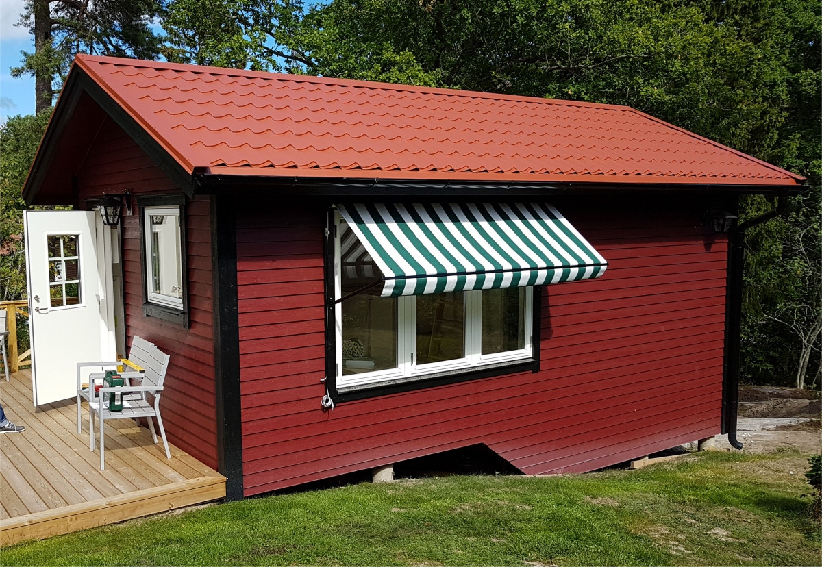
What's happened is that the house is in place and I have the following solutions:
1) My question above regarding the connection between the two floors:
You simply build a wall between the two floor frames. Same thickness and insulation as the other walls but just a few decimeters high. It was my builder who said that's how it’s done.
2) Levels etc.
The house is 6.8 m long and 3.7 m wide and is situated on a slope.
The floors in the two rooms are 60 cm in height from each other.
The living room is 365 cm long inside and the bedroom is 263 cm long and 60 cm lower.
We placed the loft floor so that there was a ceiling height of about 208 cm in the bedroom.
Above the bedroom is thus the loft, and it has a ceiling height at the centerline of 135 cm to the underside of the laminated beam.
We had planned for considerably more, but it was reduced due to the builder's requirements to build "properly."
He refused to build the roof as thin as I had planned but added, among other things, 50 mm higher roof beams to make space for more insulation while it did steal headroom on the sleeping loft. Everything must be placed downwards calculated from the ridge height of 4 m...
But we made up a bit by using a simple angle plate as a ridge instead of the ridge in tile imitation that Plannja otherwise sells for these kinds of metal roofs. Saved about 10 cm on this.
3) Ground planning etc.
After excavation to the rock that was under the soil layer, the house was placed on the slope so that the level difference would fit. We had to move the house a meter down the slope for this to work without blasting.
We set the shortest post we dared to use at the highest point under the house, and it became 25 cm.
After the construction, we backfilled with gravel and lawn on the high long side so that one corner of the house basically has the bottom of the frame level with the ground. Then it slopes with the slope so that the other corner is about 10 cm above the ground surface (the lawn).
Inside under the house, it's significantly deeper (more air between the underside and the ground surface), and there we have filled with gravel as a moisture handler.
4) Height compliance
Through these measures, we now have a ridge height above the average ground level that is just under 4 m, fulfilling the Attefall requirements.
Drawings?
@bonor I can email some drawings if you PM me your email address.
What's happened is that the house is in place and I have the following solutions:
1) My question above regarding the connection between the two floors:
You simply build a wall between the two floor frames. Same thickness and insulation as the other walls but just a few decimeters high. It was my builder who said that's how it’s done.
2) Levels etc.
The house is 6.8 m long and 3.7 m wide and is situated on a slope.
The floors in the two rooms are 60 cm in height from each other.
The living room is 365 cm long inside and the bedroom is 263 cm long and 60 cm lower.
We placed the loft floor so that there was a ceiling height of about 208 cm in the bedroom.
Above the bedroom is thus the loft, and it has a ceiling height at the centerline of 135 cm to the underside of the laminated beam.
We had planned for considerably more, but it was reduced due to the builder's requirements to build "properly."
He refused to build the roof as thin as I had planned but added, among other things, 50 mm higher roof beams to make space for more insulation while it did steal headroom on the sleeping loft. Everything must be placed downwards calculated from the ridge height of 4 m...
But we made up a bit by using a simple angle plate as a ridge instead of the ridge in tile imitation that Plannja otherwise sells for these kinds of metal roofs. Saved about 10 cm on this.
3) Ground planning etc.
After excavation to the rock that was under the soil layer, the house was placed on the slope so that the level difference would fit. We had to move the house a meter down the slope for this to work without blasting.
We set the shortest post we dared to use at the highest point under the house, and it became 25 cm.
After the construction, we backfilled with gravel and lawn on the high long side so that one corner of the house basically has the bottom of the frame level with the ground. Then it slopes with the slope so that the other corner is about 10 cm above the ground surface (the lawn).
Inside under the house, it's significantly deeper (more air between the underside and the ground surface), and there we have filled with gravel as a moisture handler.
4) Height compliance
Through these measures, we now have a ridge height above the average ground level that is just under 4 m, fulfilling the Attefall requirements.
Drawings?
@bonor I can email some drawings if you PM me your email address.
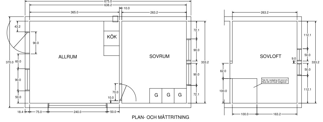
Floor plan.
The bedroom floor is 60 cm below the living room. The loft floor is 165 cm above the living room.

A creative and much more fun solution than filling and grading like everyone else is doing. I might eventually do a similar solution. But my question is, which program did you use to create the floor plan? It looked so incredibly professional.
/M
/M
Visual CADD 6 for 2D floor plans
SketchUp8 for 3D modeling of the attefallshuset
All details in the house are included in the 3D model and I have adjusted the position in the model for all parts based on measurements of where they actually ended up during construction.
Needed 2D drawings for building permits, etc., so I used my old Visual CADD program.
SketchUp8 for 3D modeling of the attefallshuset
All details in the house are included in the 3D model and I have adjusted the position in the model for all parts based on measurements of where they actually ended up during construction.
Needed 2D drawings for building permits, etc., so I used my old Visual CADD program.
Click here to reply