Hello, I am in the process of renovating our house from 1973.
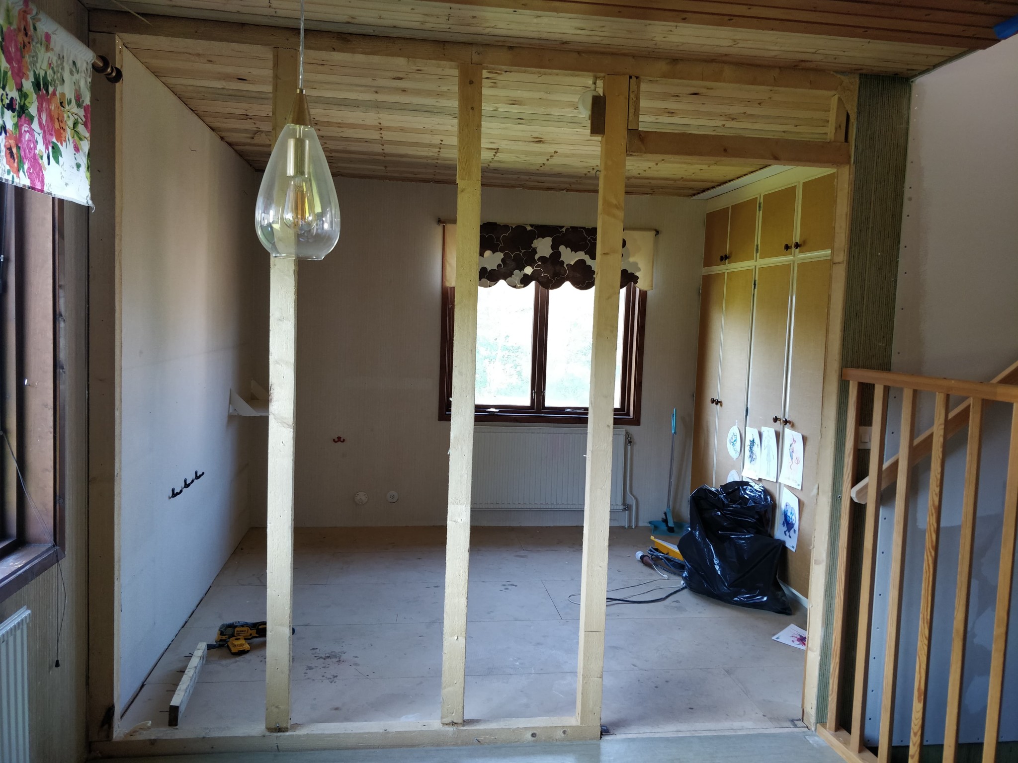
I have a wall that we want to remove. So I thought I’d do it with you if you can help me calculate what size VKR beam is needed.
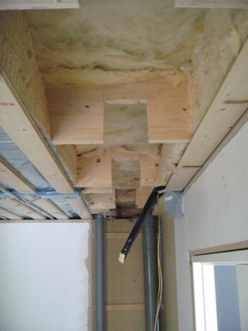
Ideally, I would like to embed the beam in the wooden joists a bit to get a smooth ceiling.
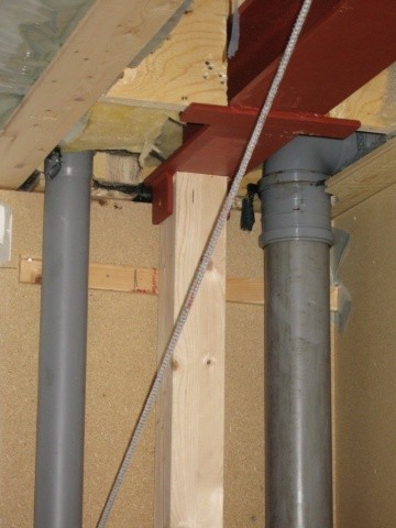
As this gentleman has thought: https://www.byggahus.se/forum/threads/faella-in-vkr-balk-i-traebjaelklag.132894/
Currently, there are 70x70 studs distributed over 4 pieces.
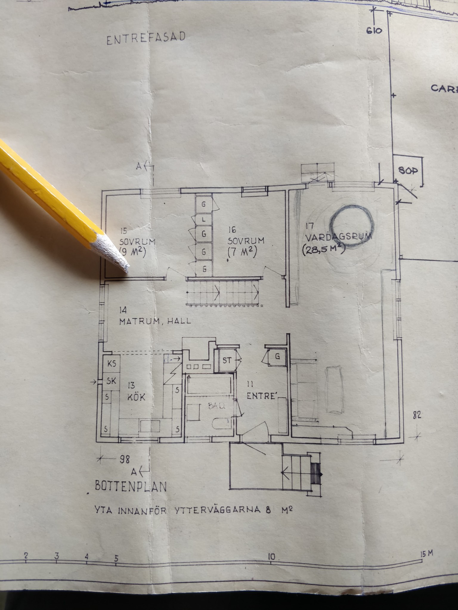
The length of the VKR beam will be 263 cm
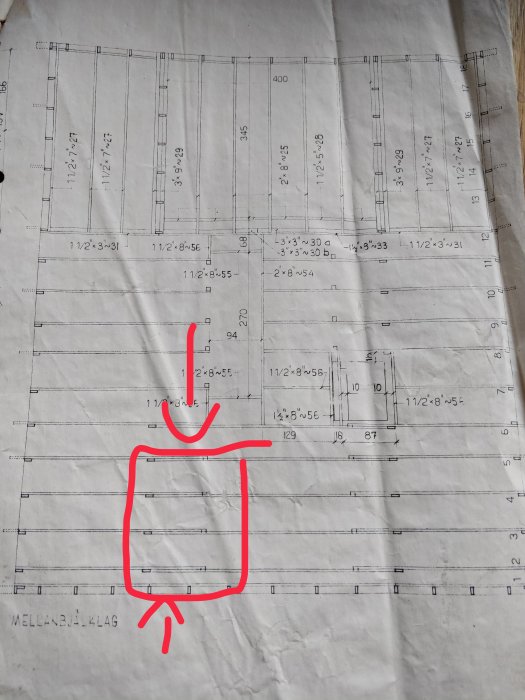
The span of the wooden joists is 850 cm
The wooden joists are 45x195 cm
The house is 1.5 stories with a basement.
A section with dimensions and information on the snow zone is also needed to calculate the loads. Why do you want an VKR beam? They are not intended for that size of loads that are relevant. Embedding the beam in the floor is less suitable because the joists are joined over the wall. Additionally, it's unnecessarily complicated.
You need a section with dimensions and information about the snow load zone to calculate the loads. Why do you want a VKR beam? They are not intended for the size of loads that will be relevant. Embedding the beam in the floor structure is less suitable since the joists are joined over the wall. Additionally, it is unnecessarily complicated.
I think a VKR beam is more compact than a glulam beam.
But I agree with you that it is a bit more complicated work. However, if it works, it's the neatest, and you get a smooth ceiling.
Is the alternative to use a glulam beam in an appropriate size?
A more efficient (and suitable) steel profile is, for example, an HEA profile. It is much stiffer and stronger than a VKR profile of the same height. As mentioned, it's a relatively extensive operation to recess the beam, but I agree that a smooth ceiling looks much nicer. Personally, I would have made it more complicated and hidden the beam in the ceiling
A more efficient (and suitable) steel profile is, for example, an HEA profile. It is much stiffer and stronger than a VKR profile of the same height. As mentioned, it is a relatively extensive operation to recess the beam, but I agree that a smooth ceiling looks much nicer. Personally, I would have complicated it and hidden the beam in the ceiling
How would you go about complicating it and hiding the beam? And what dimension of the beam would you aim for?
A small miscalculation, it's difficult to fit an I-beam since the flange is in the way
One could create a combination of an as narrow as possible rectangular VKR on the plate and a T-profile that is inserted into the floor structure. You should check that the floor structure and truss work when cutting the overlap. You could also check how much it is appropriate to notch out the beams at the bottom. That way, you could raise the VKR somewhat and then lower the suspended ceiling to remove it.
The beams are probably rigidly spliced. I don't think one should put the compensating beam in the floor structure. I don't find it particularly disturbing to have a beam in the ceiling. I never go looking for errors in the ceiling, perhaps it's an age symptom...
A good start is to check if the beam system works even if the overlap is broken. If the answer is no, one should consider if it's worth needing to reinforce the beam system just to fit in the beam.
Hopefully, it's an age symptom because I'm starting to get neck issues from looking at ceilings and searching for all visible deflections
Exactly, it makes a big difference if the wall is removed. The idea is that it should become part of the kitchen.
Do you have to hire an engineer to calculate it?
What I mean is that a beam of 2.7 meters is not very long. So maybe you can, with both belt and braces, say that, for example, a HEA180 beam would work perfectly for the purpose?
It is not a good idea to guess as long as all conditions have not been clarified. The difference between the highest and lowest can be significant. A sectional drawing and information about the snow zone is a good step on the way.
You need to submit a building notification for Interventions in the load-bearing structure and depending on the municipality, it may be required to show a calculation on how to size beams and pillars.
It is not a good idea to guess as long as all conditions are not clarified. The difference between the highest and lowest can be significant. A sectional drawing and information about the snow zone are a good step in the right direction.
Jjustusandersson said:
It is not a good idea to guess as long as all conditions are not clarified. The difference between the highest and lowest can be significant. A sectional drawing and information about the snow zone are a good step in the right direction.
Hello again. It has been a while
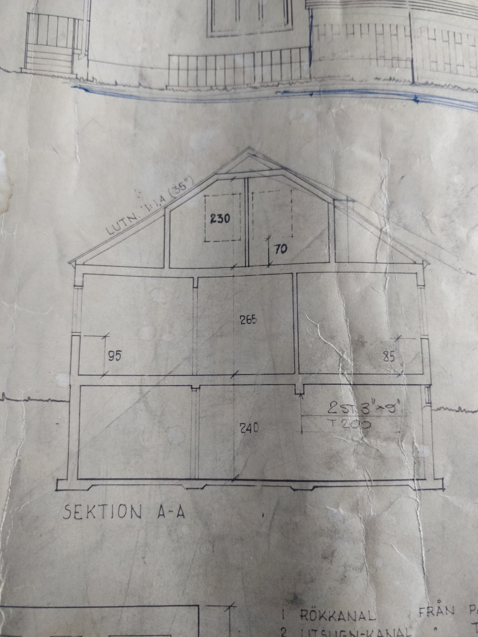
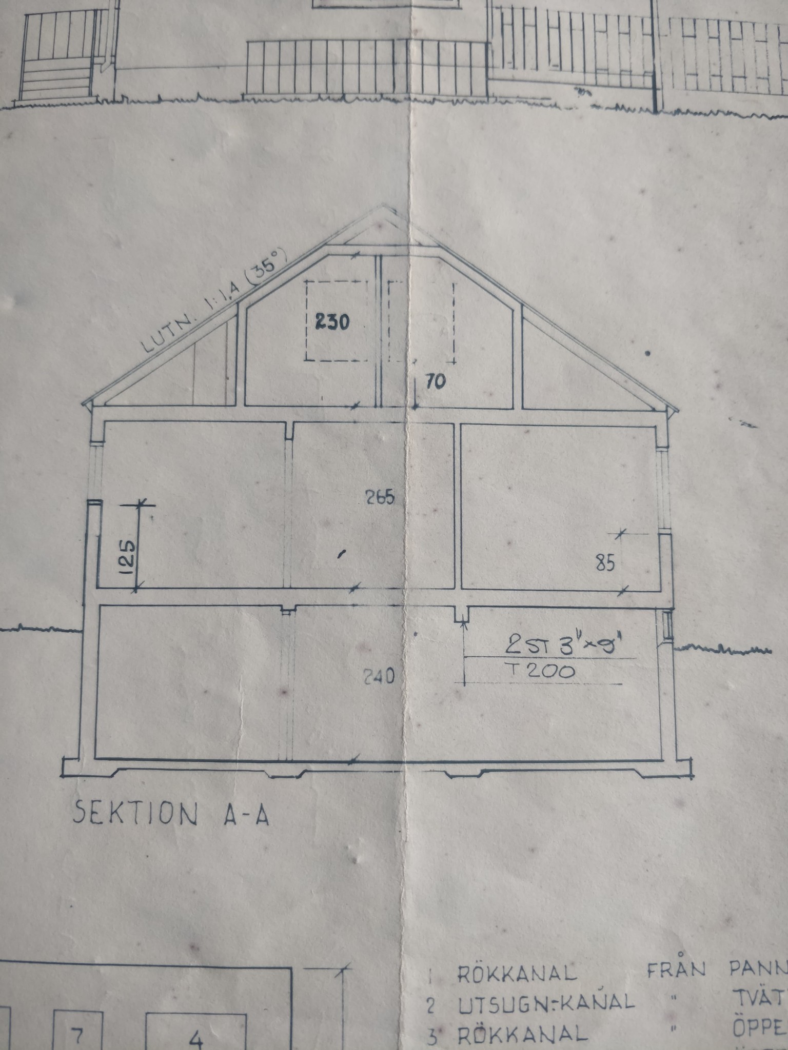
We live in the Gothenburg area. So it is snow zone 1.5
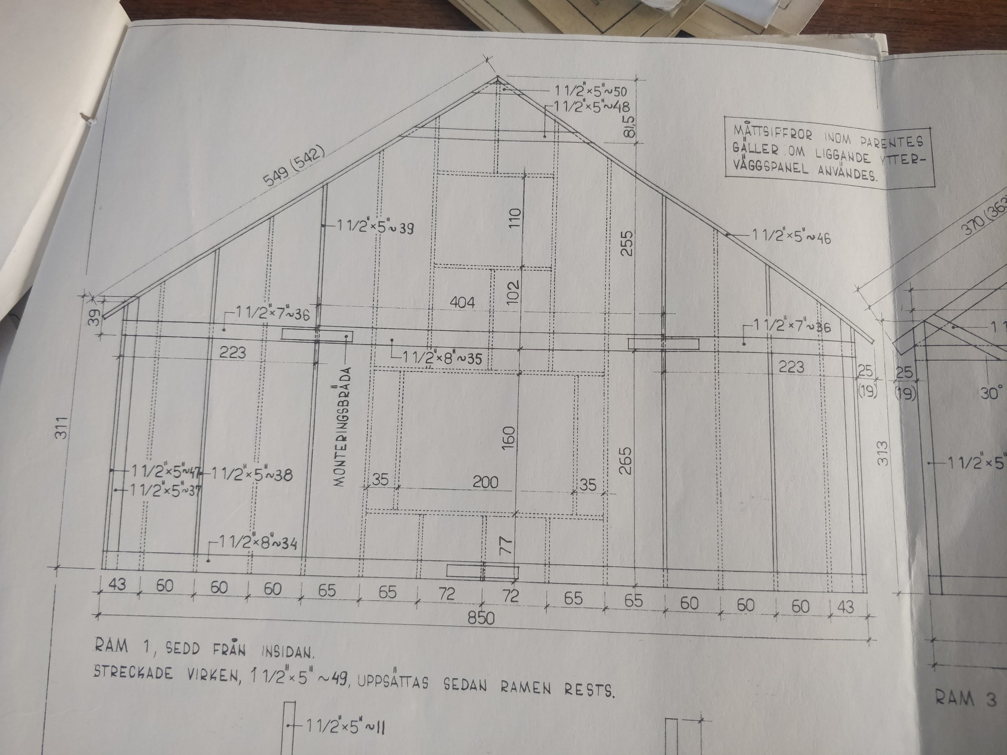
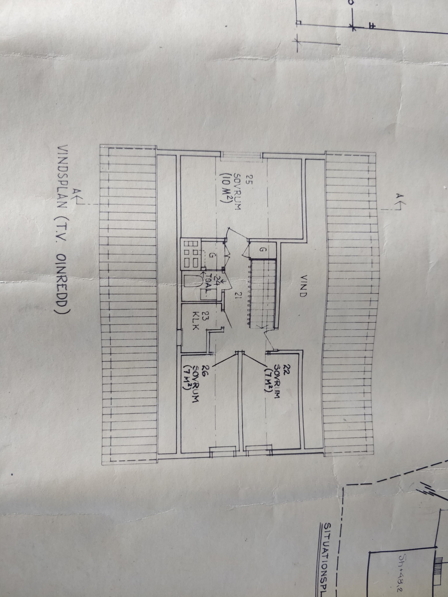
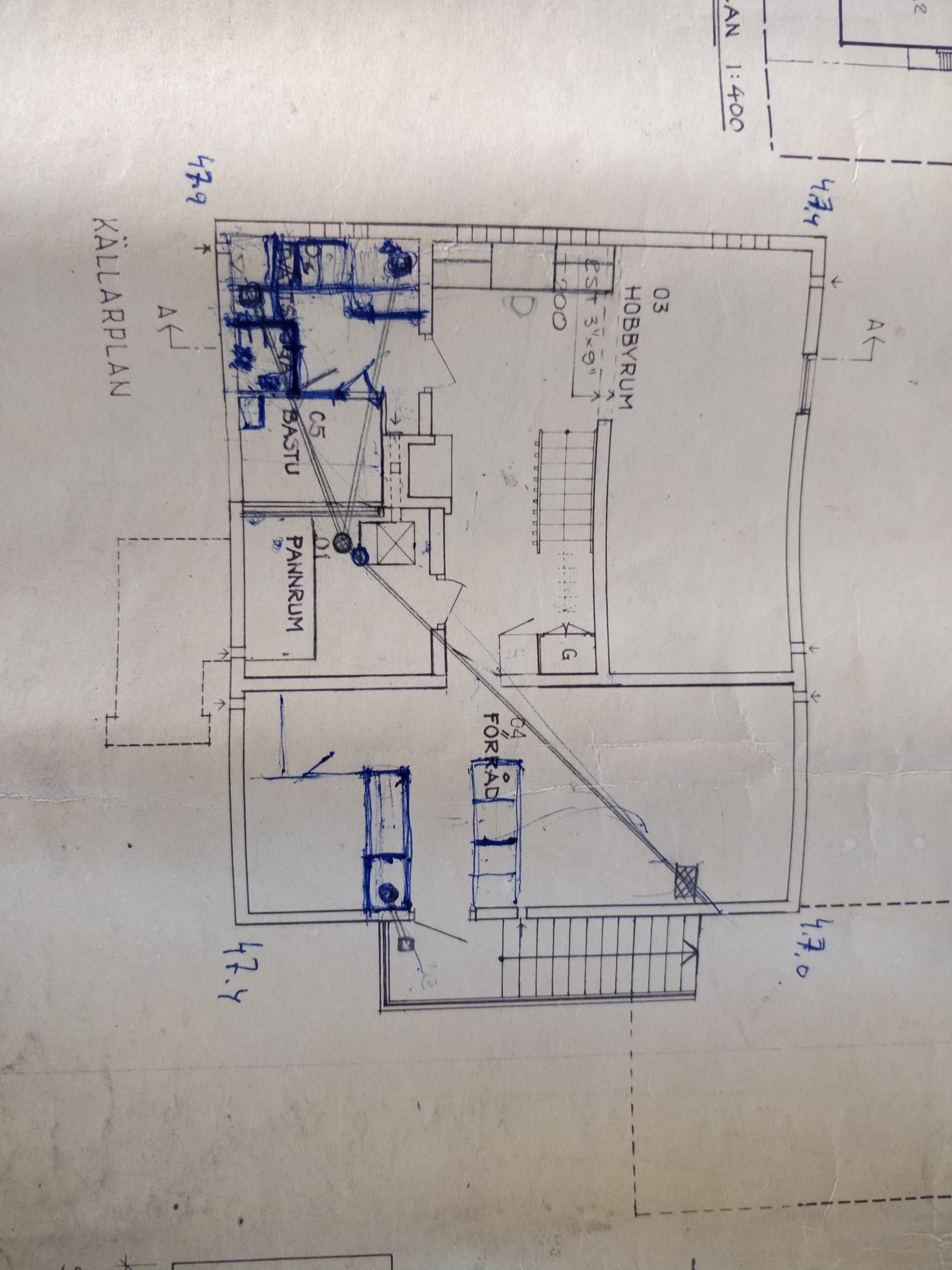
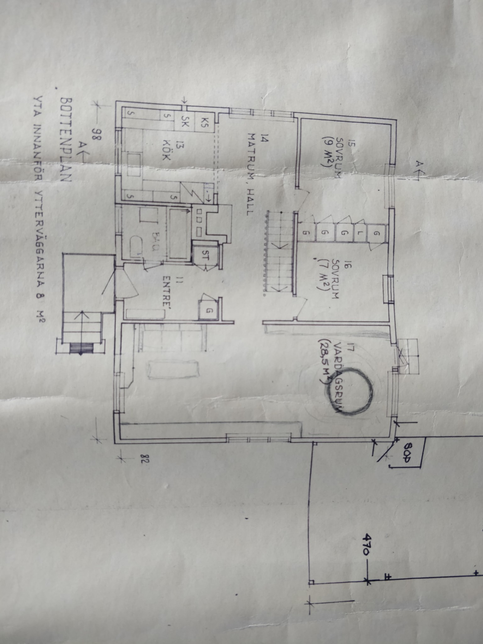
Here are some Sectional Drawings. I hope they are satisfactory.
I have talked to a friend who is a Construction Engineer working in construction operations. He said that an HEB200 works.
So I've been pondering and thinking about how to proceed to make it look the best. I found an existing thread on byggahus
how he did it.
So I think it should be possible to do the same but instead of just putting a flat iron at the bottom that the joist rests on, I will weld on a custom-made joist hanger in the Heb200 beam. So that you can fasten the joist properly and it can't twist.


")