I will install and load a steel beam that is 6m long and simply supported at both ends with two static loads 2m from one support and 2m from the other support, symmetrically in relation to the supports. The load is option 1: approximately 22 kN at each load point, option 2: approximately 15 kN at each load point. I can accept a deflection of about 30mm. Which dimension of steel beam should I choose, and I would also be grateful if someone could provide me with a formula for how to easily calculate deflection without considering lateral-torsional buckling and shear, just length, static load, and steel support beams. Glue-laminated timber beams are not an option. ljungdahl@comhem.se
Take a look at this page and maybe it can help you.
http://www.aps.anl.gov/APS_Engineering_Support_Division/Mechanical_Operations_and_Maintenance/Calculators/ElasticBeam2.html
http://www.aps.anl.gov/APS_Engineering_Support_Division/Mechanical_Operations_and_Maintenance/Calculators/ElasticBeam2.html

Hello,
Okay, then only the higher load is relevant. Since I have specified the maximum acceptable deflection, I consider that I have a safety factor in this, I don't think it will ever be relevant with a higher load.
Okay, then only the higher load is relevant. Since I have specified the maximum acceptable deflection, I consider that I have a safety factor in this, I don't think it will ever be relevant with a higher load.
It depends on what load (stress) this deflection causes. If you are close to the yield strength for this load, you have no safety factor at all.
According to standards for cranes, the maximum deflection should be less than 1/1000 of the span for a straight traversing beam for a crane. In your case, it would be 6 mm, so from that perspective, you have 5 times more deflection than allowed for a crane. If you have camber on the beam, a maximum of 1/500 of the span applies. For floors with larger spans (>4m), 1/600 is specified, which in your case gives 10 mm.
For an overview of design according to Eurocode, you can look at the following page:
http://www.kstr.lth.se/fileadmin/kstr/pdf_files/externkursEK/Eurocode-kurs-2010-10-04__Kompatibilitetslaege__01.pdf
Safety factor is calculated against the ultimate limit state, not against the yield point...hecke said:It depends on the load (stress) caused by this deflection. If you are close to the yield limit for this load, then you have no safety factor at all. According to standards for cranes, the maximum deflection shall be less than 1/1000 of the span for a straight crane girder. In your case, it becomes 6 mm, so in that aspect, you have 5 times more deflection than is allowed for a crane. If you have a camber on the beam, the maximum is 1/500 of the span. For floors with a larger span (>4m), 1/600 is specified, which in your case gives 10 mm.
For an overview of design according to Eurocode, you can look at the following page:
[link]
The conditions you have specified require that the beam must have a moment of inertia of at least 26772487 mm^4. The beam closest to this is an HE200A. With this, you get a deformation of 25.4 mm and a stress of 113 MPa. The weight of your beam will be 262 kg. The beam is supported by 100 mm at each end with a free length of 6000 mm. The load is distributed over a centered section of 200 mm with a cc of 2000 to the outer free end.
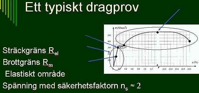
There are many different definitions of a safety factor, but for simple linear elastic calculations, it is not uncommon to use the yield limit as the permissible load and derive the safety factor from it. See the definition of ns below in the image. The reason is that residual deformation is usually not an acceptable condition for a structure.
In other contexts, when for various reasons you must utilize the material to its fullest in your design, for example, a probabilistic risk assessment can be conducted against primarily crack initiation due to LCF or TMF for a number of load cycles, and also calculation of crack propagation with linear fracture mechanics until a critical crack length occurs. In such cases, the probability of failure after a number of cycles is specified instead of a simple safety factor. However, this is a bit advanced for this context and requires a level of knowledge that cannot be conveyed in a forum like this. When you do not have full control over your calculations, loads, or material data, I advocate designing with a certain safety factor against the yield limit instead of against failure.
In other contexts, when for various reasons you must utilize the material to its fullest in your design, for example, a probabilistic risk assessment can be conducted against primarily crack initiation due to LCF or TMF for a number of load cycles, and also calculation of crack propagation with linear fracture mechanics until a critical crack length occurs. In such cases, the probability of failure after a number of cycles is specified instead of a simple safety factor. However, this is a bit advanced for this context and requires a level of knowledge that cannot be conveyed in a forum like this. When you do not have full control over your calculations, loads, or material data, I advocate designing with a certain safety factor against the yield limit instead of against failure.
Click here to reply