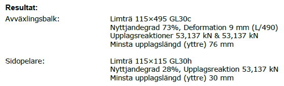
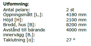
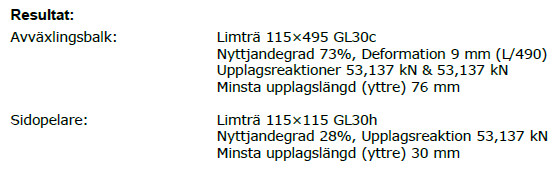
I'm exploring the possibilities of opening up an exterior wall for a glass section in my 2-story house and have done some preliminary calculations with the timber guide. The suggestion below is a glulam beam of 115x495, resulting in a deflection of 9mm (L/490).
However, such a glulam beam won't fit. I'm therefore considering what deflection an IPE 300 would yield with the same data.
It should be possible to calculate the load value from the timber guide and use this value for the deflection of a steel beam. Or am I thinking wrong? I get some very low numbers... maybe it's what's indicated as "Support reactions 53.137 kN & 53.137 kN" that's making me unsure. I understand this as the breaking limit and not the load value, am I wrong?
- q should therefore be 25.94 kN/m for the glulam beam for the deflection to be 8.5mm
- using the same q for an IPE 300 should make the deflection 6.6mm
Am I thinking wrong?
If I use support reactions 2x53.137kN/m, the deflection becomes 24mm for IPE 300... That weight feels completely foreign unless the entire house is supposed to rest on the beam...
I pondered overnight and realized that the reactions given as 53.137 kN & 53.137 kN align with my own calculation of q, if I just divide by L... (missed the part about kN/m...)
- q from the reactions then becomes: 28 kN/m
- q from own load calculation (with 19.2m2 roof and 16.7m2 floor/2, live load 2.0kN): 21 kN/m
This fits better with the q values obtained if I work backwards from the timber guide for some different dimensions: 23-29 kN/m
Gives deflection 4.7-6.4mm
Am I thinking correctly here?
Line load, or q, on the beam is indeed the sum of the support reactions divided by the beam's span. The support reactions are presented in the failure in their execution, and all loads are multiplied by partial coefficients, which makes their load somewhat greater than what you calculated in your example.
The support reactions are reported in terms of their ultimate strength, and all loads are multiplied by partial coefficients, which makes their load slightly larger than the one you calculated in your example.
So I'm not completely lost, but need to include partial coefficients. I've seen in formulas that γm and γnare included in fyd and consequently Mrd, but how do I calculate with γ in deflection? I haven't found a good example of that yet.
Without complicating things too much, the loads should primarily be multiplied by partial coefficients so that you obtain a line load in the ultimate limit state and a line load in the serviceability limit state. The line load you obtain in the serviceability limit state is used to calculate the deflection of the beam. I would recommend using a characteristic combination and limiting the deflection to a maximum of 10mm since you will have a glass panel underneath.
The load in the ultimate limit state is used to design the beam so that failure does not occur. Often there are usually no problems for these types of constructions as the deflection still determines the dimension of the beam.
I realize the answer is a bit messy, but there is quite a bit to consider if the standard is to be followed
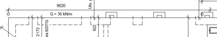
I have obtained the basic drawing of the house where the line load for the current wall is included, Q=36kN/m. Significantly higher than the 21-28kN/m I previously calculated. But perhaps partial coefficients have been considered in this value, or it shows what the foundation slab is designed for. I cannot reconcile this load with the existing beam (115x225) in today's opening of 2390 mm (2570 mm including posts). This would lead to a deflection of 18 mm, but it would likely not hold, and according to the wooden guide's design tool (with only 26kN/m), the smallest beam is 140x225... I need to reduce the line load to just under 20kN/m for that beam to be acceptable according to the design tools. So, close to what I get if I calculate the loads myself based on the area of the floor and roof (including snow 2.5kN/sqm). But since the line load is shown on the drawing, this is what I must adhere to, I suppose.
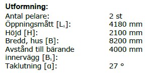
A line load of 36kN/m would result in an entirely acceptable deflection of 8 mm with an IPE 300 (4180 mm), but with a support reaction of 75kN, there might be issues with point load for the edge beam of the slab. I'm not planning to tackle the slab, so right now it feels like curtains for my small project...
The line load specified on the ground plan is at 99% safety in failure. And it should be in safety class 2. Is there any text on the drawing somewhere that certifies this, do you think?
Load in the serviceability limit state usually ranges from 50-80% of the failure point depending a bit on how the distribution looks between self-weight and snow/useful load. In your case with a light construction and both snow and useful load, I would guess you are closer to 50% than 80%. Thus, the service load would be around 20-25 kN/m, which matches pretty well with the existing support you mention.
In failure, the support reaction becomes 75 kN on the edge beam as you write. It could be good to check the edge beam against this load.
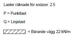
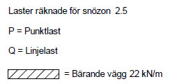
No text other than that Q refers to line load.
I've sent the question to the house supplier asking what Q=36kN/m refers to. If it is the ultimate limit, I can continue, but if it is the maximum line load from the house, then the point load of 75kN will be too high for my edge beam. Now I'm keeping my fingers crossed that the house supplier responds.
Received a clear response from the house supplier, but unfortunately not the answer I wanted...:
"The Q-value is the maximum line load from the house for which the foundation contractor then makes their own design for the foundation. I double-checked the line load again and it comes to 36 kN/m, 21 kN/m comes just from the roof trusses, then the floor layer has an additional 10 kN/m due to the bathroom and we count with leveling compound and tiles, etc., then self-weight from the wall is about 2 kN/m on each floor."
This results in too high a point load for the edge beam (around 75kN), so now it's time to rethink (or stop thinking...). By placing posts between the windows, I can reduce the point load, but it probably requires three intermediate posts to get below the point load that the current posts provide (the current opening is 2.4m). Unfortunately, parts of the old beam must then be removed, which will be difficult without causing damage to the outer plasterboard and wood facade. With intermediate posts at 90x90, it also won't look entirely elegant. Then it will be more than twice as expensive as I cannot reuse the old windows. The new solution doesn't appeal, so I'll see how or if there will be a continuation.
Click here to reply
Vi vill skicka notiser för ämnen du bevakar och händelser som berör dig.


Aron Roger said:
") but need to include partial coefficients. I've seen in formulas that γm and γn are included in fyd and consequently Mrd, but how do I calculate with γ in deflection? I haven't found a good example of that yet.
but need to include partial coefficients. I've seen in formulas that γm and γn are included in fyd and consequently Mrd, but how do I calculate with γ in deflection? I haven't found a good example of that yet.