Plaster builds up more than paint, so paint might be preferable. However, the fireproof paint is less smooth on the surface and relatively sensitive to mechanical impact.
Good to know. It will be protected in the staircase, so there's little risk of impact. The surface is something to consider, and a protruding plaster box from the wall would also look strange.
You might want to double-check with the designer to avoid any misunderstandings. Isn't it 3m between the ridge and the floor construction, or what did you mean with the question regarding smaller dimensions?
Yes, it is 3 m between the ridge and the floor construction. But the drawing is calculated for over 7 m if it is supposed to go down to the basement.
The 7m long column is likely considered braced at floor level, hence the dimension. Will the column be located in the wall between the staircase and the kitchen?
The 7m long column is likely calculated as braced at floor level, hence the dimension. Is the column going to be in the wall between the stairs and the kitchen?
Yes, but not in the corner since the wall along does not stand on the basement wall but a bit further inside the house.
You might want to double-check with the contractor to avoid any misunderstandings. Isn't it 3m between the ridge and the joist or what were you thinking about with the question regarding a smaller dimension?
that would of course be the best. but for various reasons it's difficult. so in that case we might bring in a new one and then they will probably want to calculate the entire construction to open up to the ridge before they put their name on it. It’s not really a problem, but it feels a bit unnecessary and the time is a bit short.
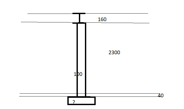
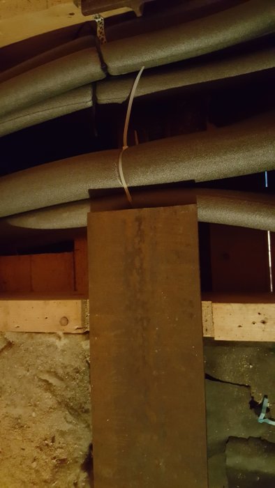
Unfortunately, no more drawings. But for some reason, on top of the basement wall included in the original drawing, there is an H beam. The designer who drew for us saw absolutely no reason for it. The house was bought as a kit, and the beam is not included. So it was added in the meantime. We have two theories. One is that the previous owner who built the house and the neighbor built at the same time. The neighbor was a very confident man, and they have a steel beam in their house, but no wall underneath for support, so theory one is that the neighbor said he must have a beam. The second theory is that the basement wall did not end up exactly in the middle, and they added the steel beam, which is slightly, about 5 cm, shifted to the left (if you look in the direction of the drawing). Here too, I believe it is at the neighbor's suggestion.
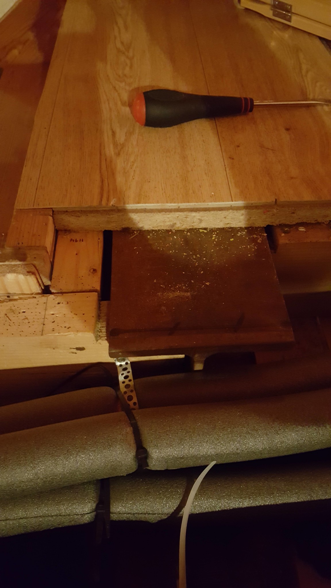
We have cut it off in one place to run radiator pipes. The beam is 160x160 and the material thickness is about 11 or 12.
What I wonder is why the designer suggested that 115x115 glulam should be replaced with a VKR 80x80? It's a bit like replacing a toothpick with a flower stick.
He probably went for a larger size to avoid liability since he didn't do the calculations. But do you mean that we could reduce it more? The narrower, the better for us, of course. I'm not asking you to say anything for sure, but if you think it's possible, it would definitely be worth bringing in another designer for a look. What dimensions would you suggest otherwise?
P.S. I remembered he said we needed one this large considering the buckling length and that a narrower post would be too sensitive to side movements.
bossespecial is the expert here. You can trust what he writes. I just made a simple comparison for fun. The comparison measure EI (i.e., the product of the modulus of elasticity and the moment of inertia) is about three times as high for VKR 80x80x7.1 as for glue-laminated timber 115x115. Even a 70x70x5 can handle more than a 115x115 with the same buckle length. When I see a behavior that I don't understand, I wonder why? This suggests an unreported thought.
Now let's see if I understand it correctly, the H-beam is therefore parallel to the ridge and is offset 50mm to the left (towards the TV bench) from the center wall in the basement on the original drawing? If so, how does the column relate to the wall?
Two experts in the thread, fantastic!
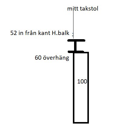
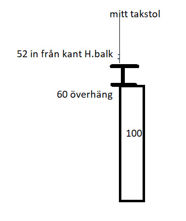
This is how I mean it looks. We don't know exactly where in this the middle of the truss hits (but I can find out over the weekend).
here's what it looks like: the center of the truss hits 52 mm from the left edge of the H-beam. The H-beam is shifted 60 mm to the left. In the wall, the center of the truss is about 170 mm from the corner.


")