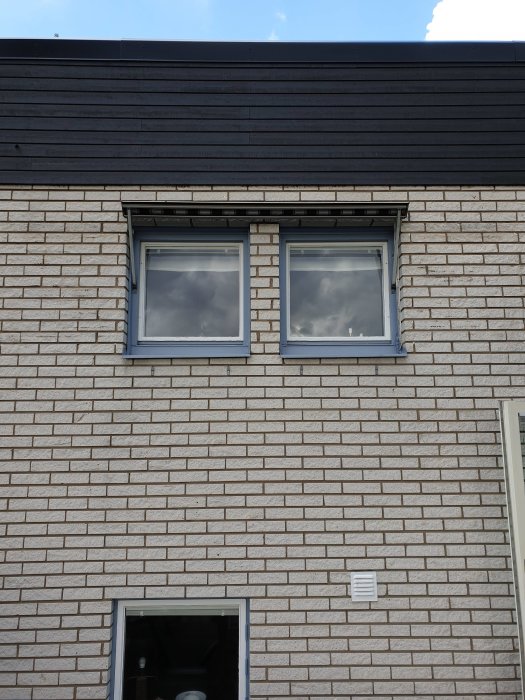
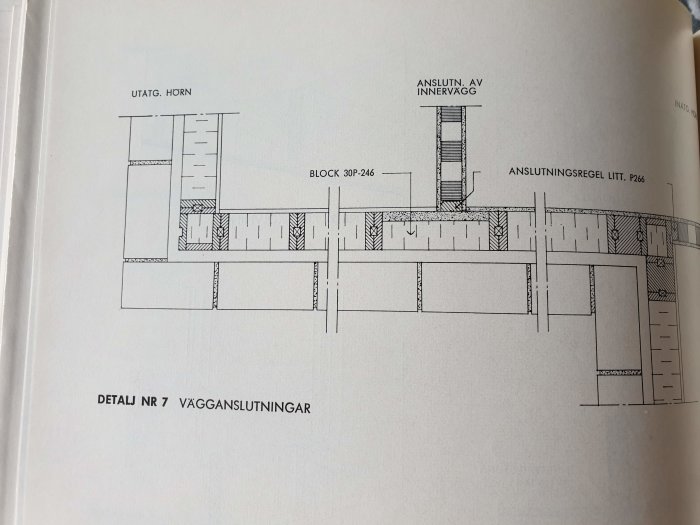
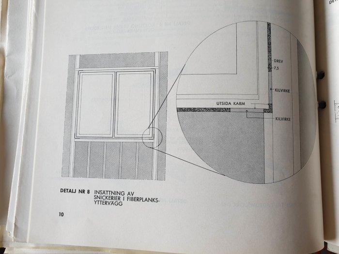
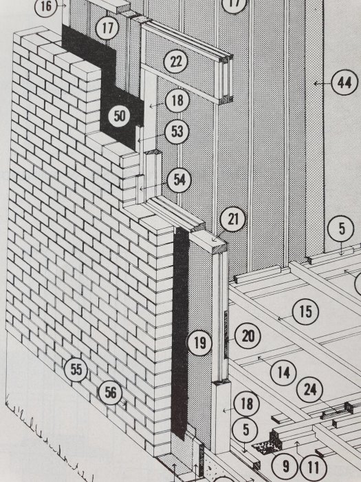
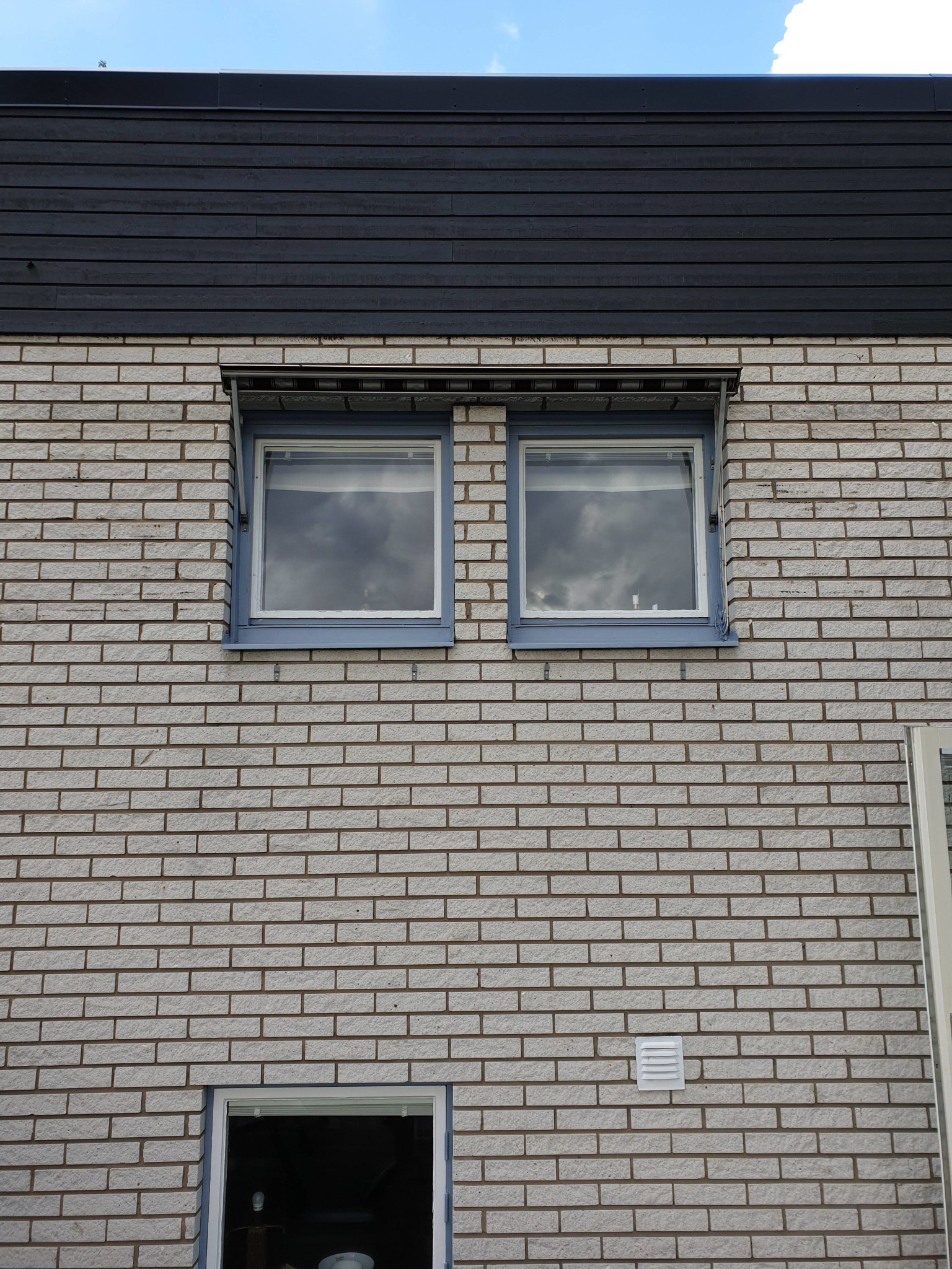
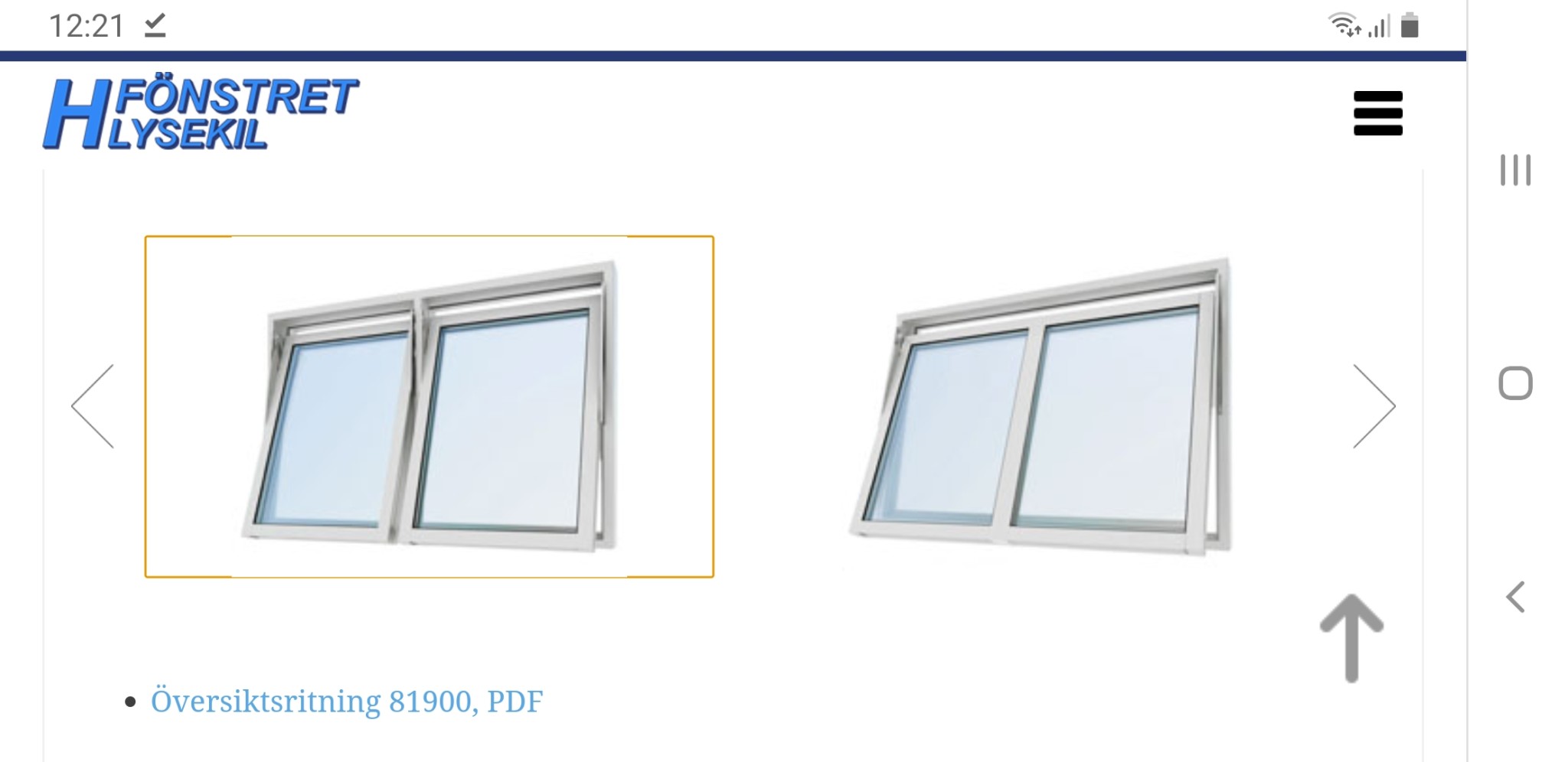
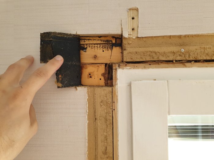
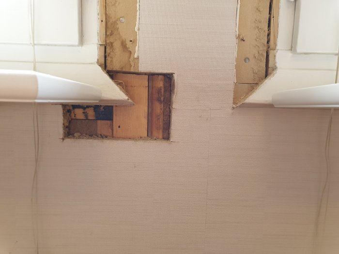
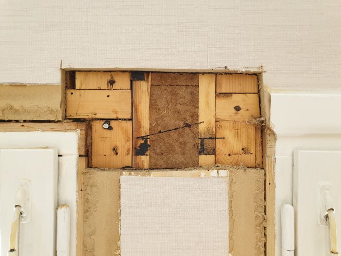
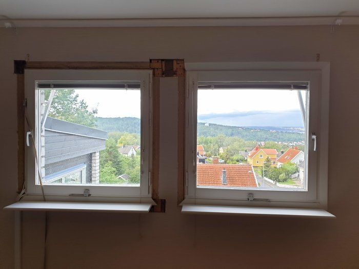
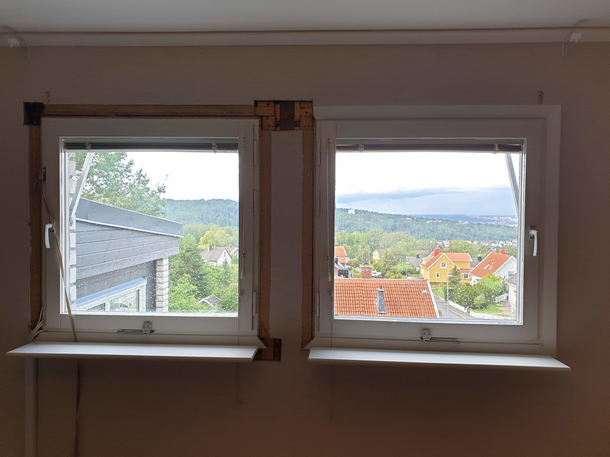
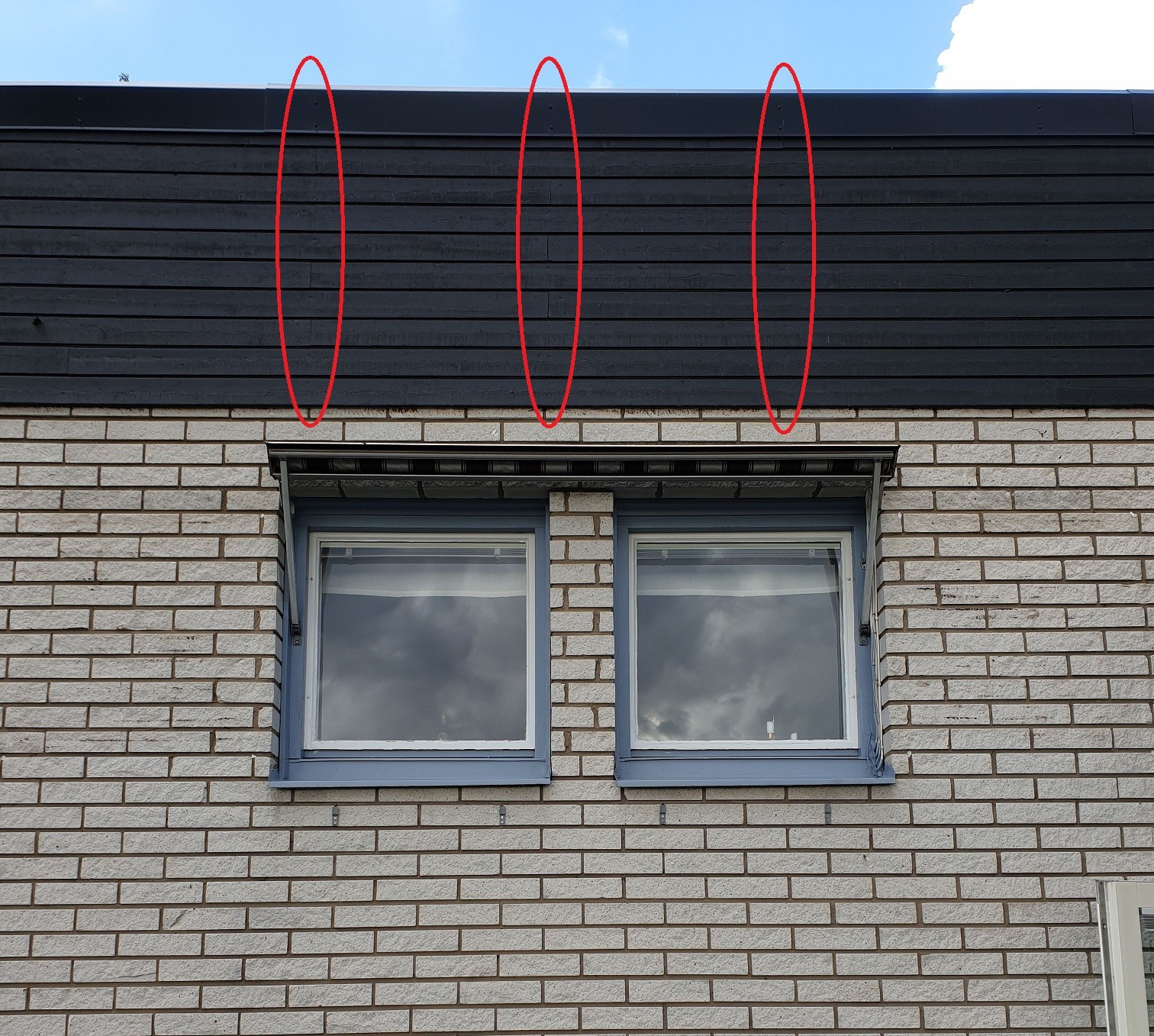
My question now is what alternatives do I have for the brickwork above the window? There will be a "free-hanging" section of 2m (4 rows high) over the window, and I suspect I will somehow need to build a hidden "shelf" for the bricks. What solutions are available? Maybe a metal angle profile of about 60x60mm?
I will probably also need to place a supporting beam inside the wall behind the bricks of about 3m. This is the wall on which the roof trusses rest. C-C for the roof trusses is 900mm.
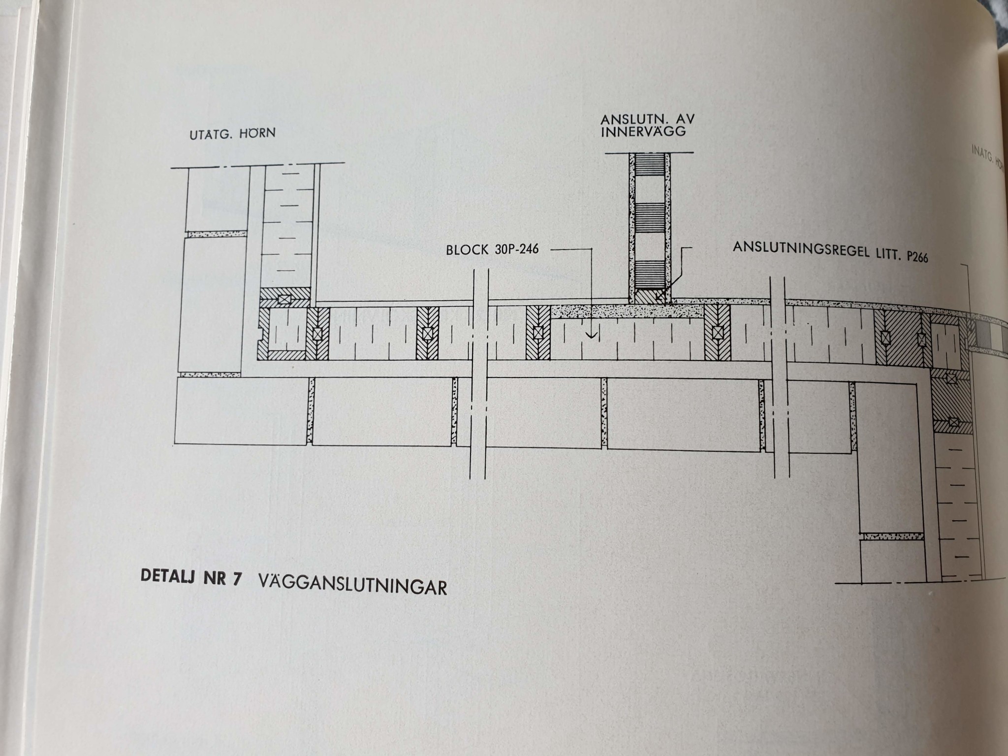
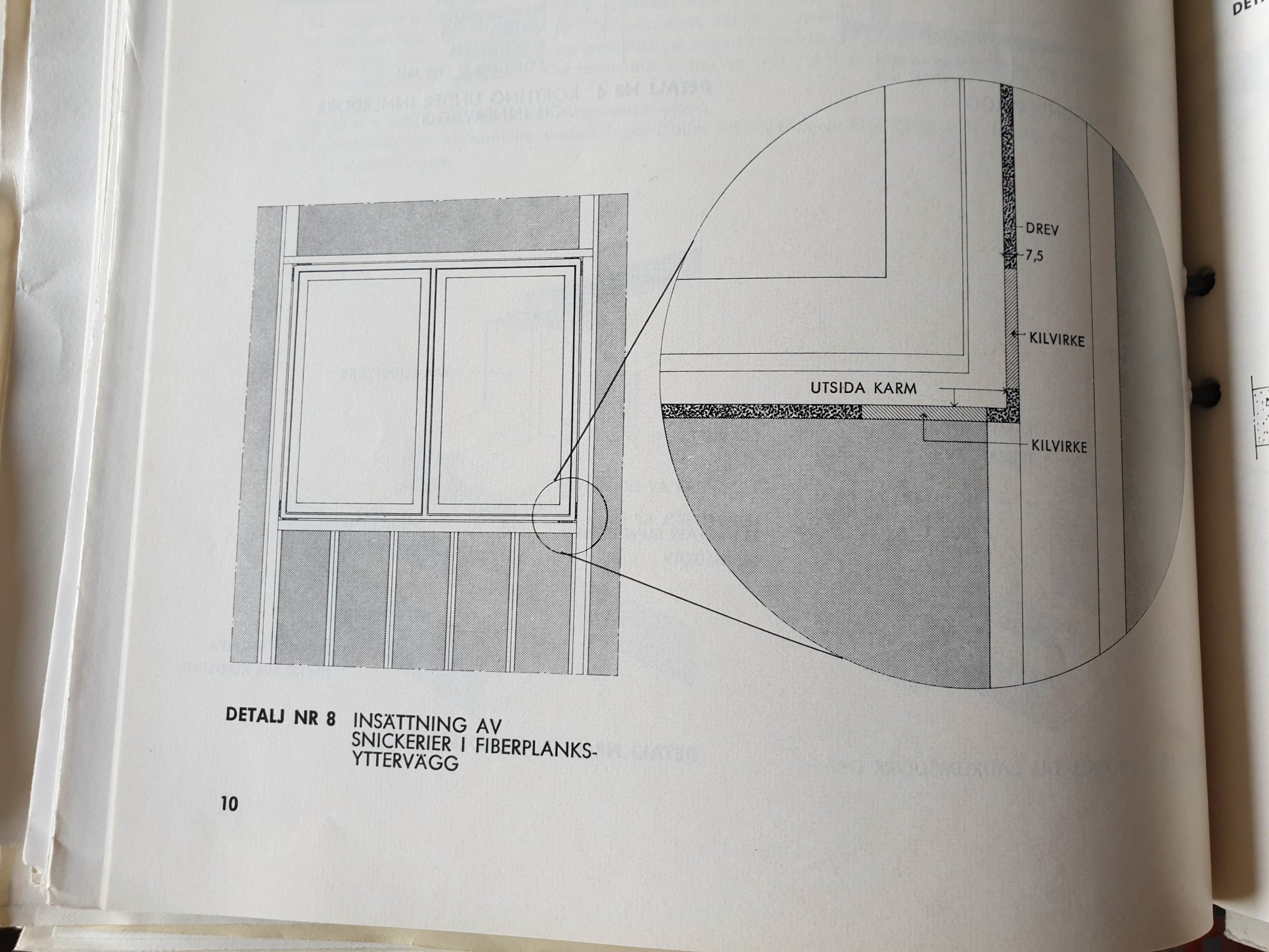
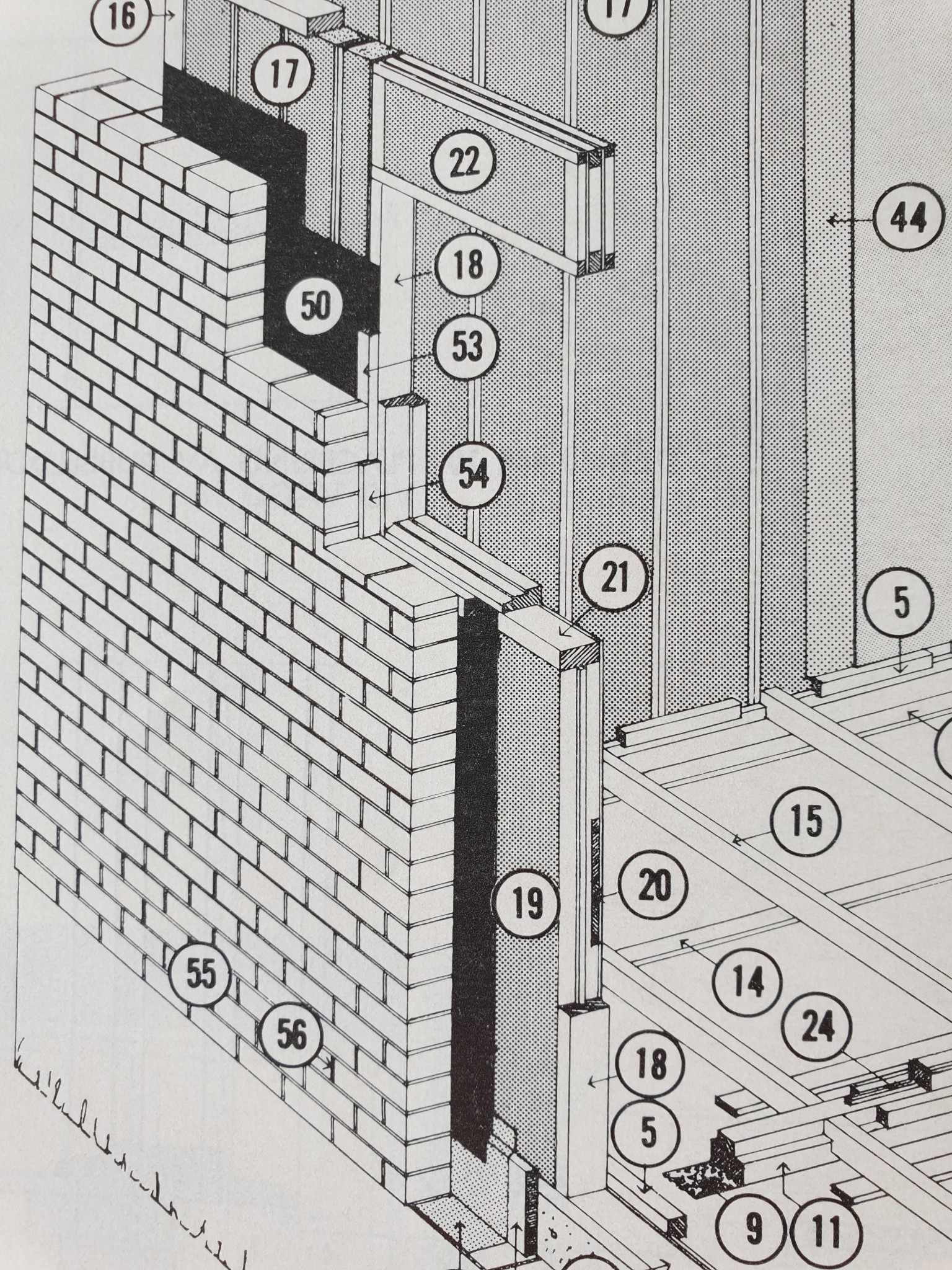
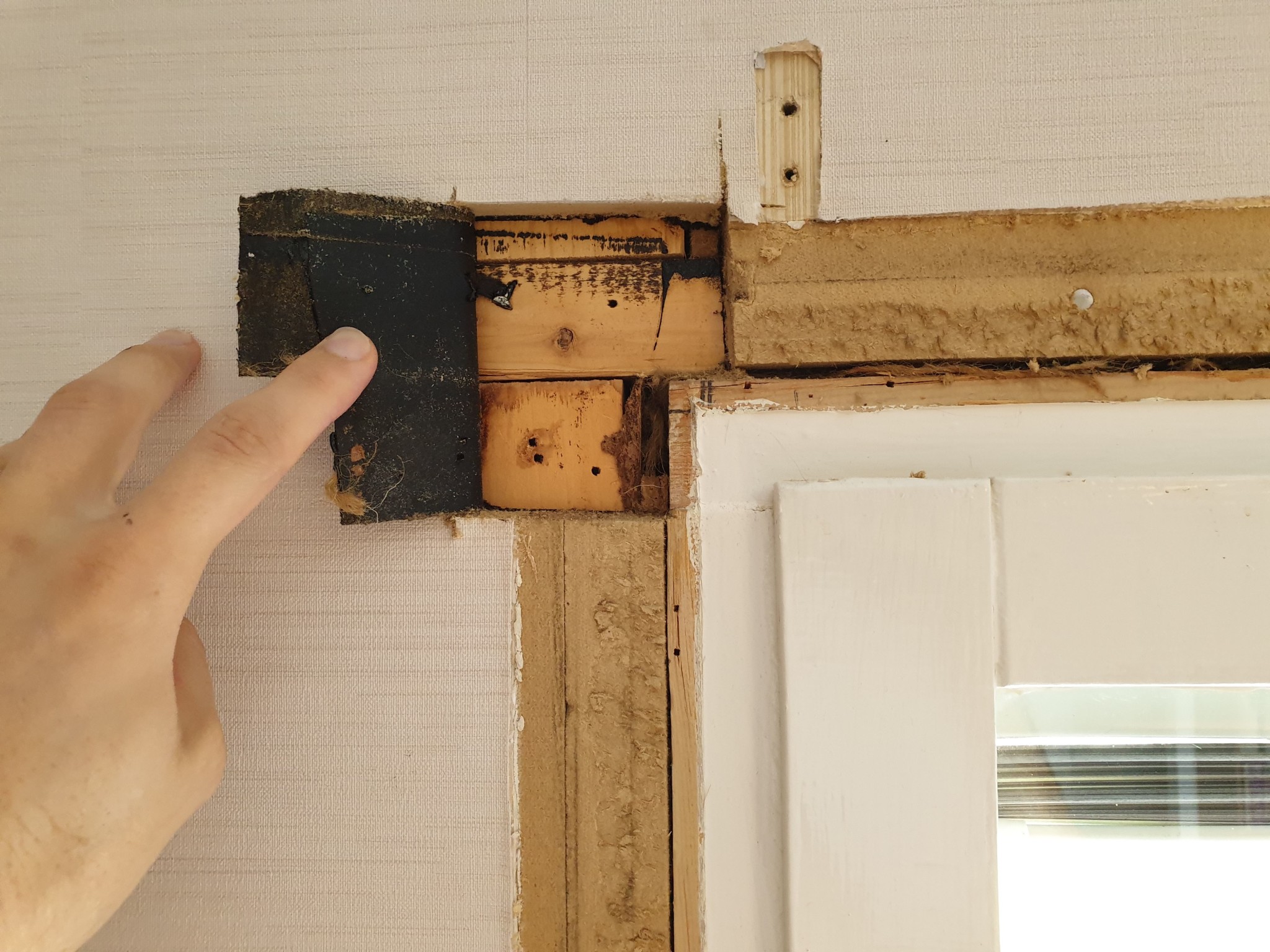
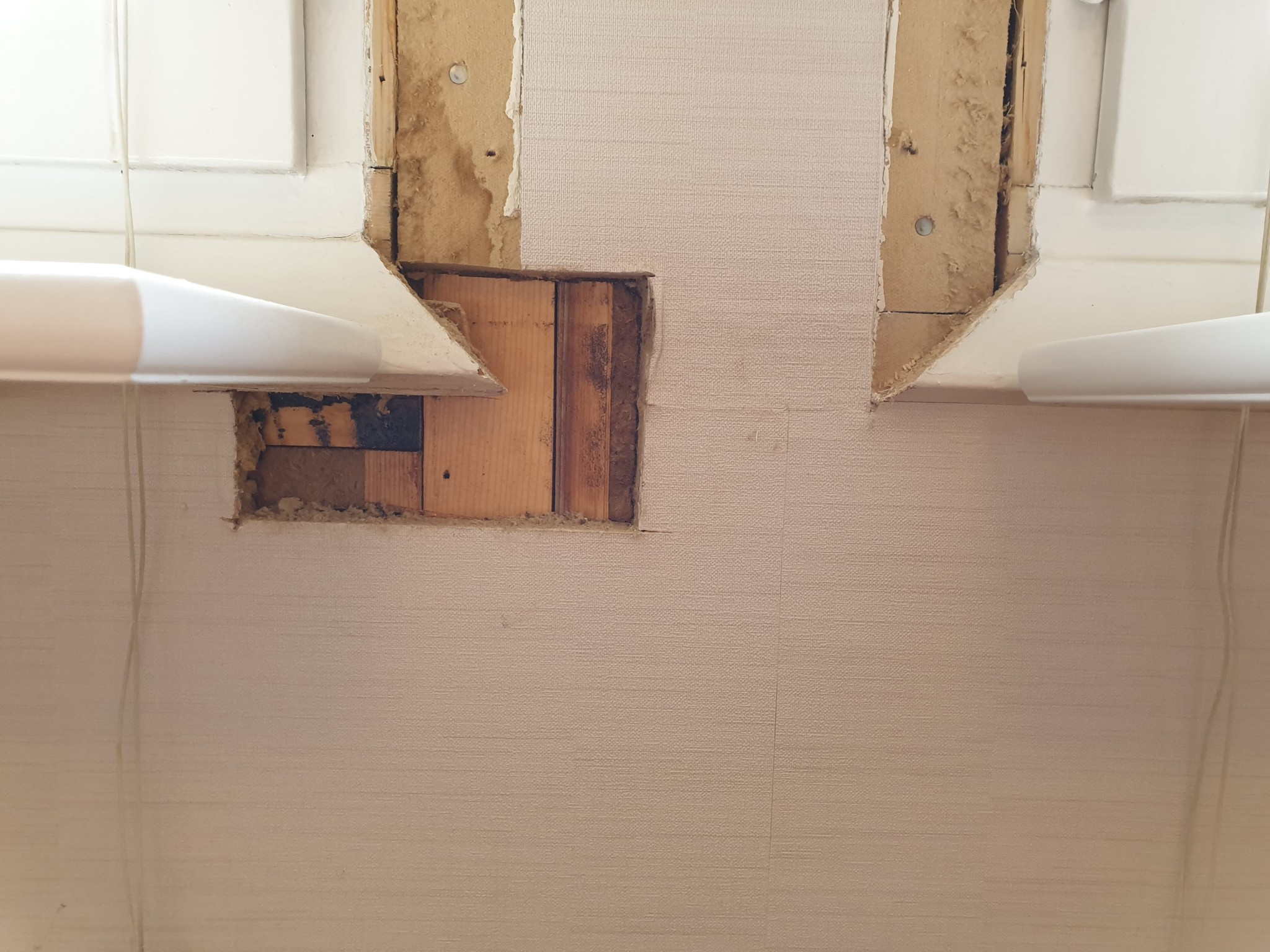
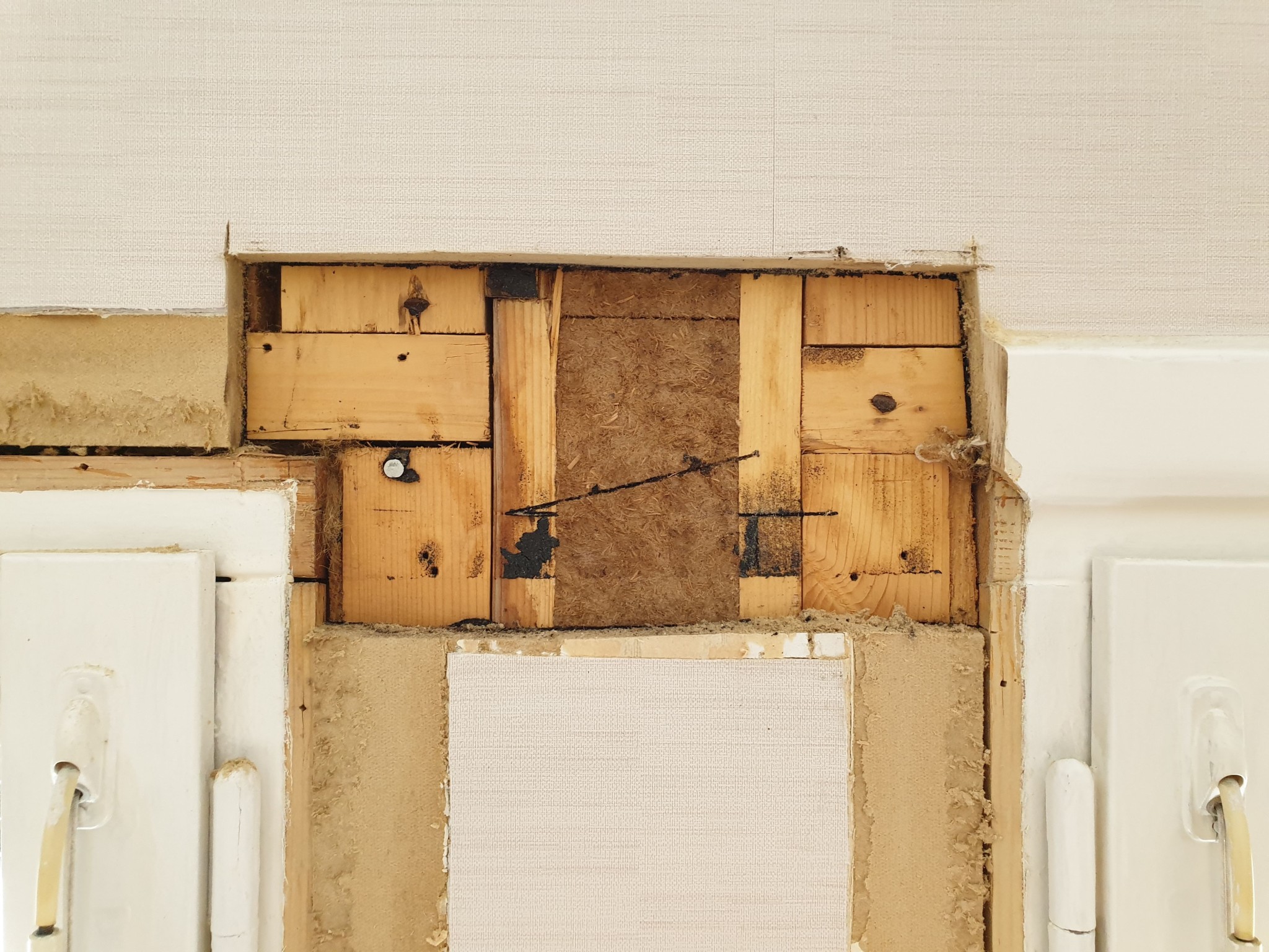
I have now created a series of inspection holes in the interior wall to check how it is framed around the windows. It seems to be built just according to the illustrations in my first post. So I am now planning to remove the two upright studs between the windows and instead put up a beam (glulam I assume, or a stud?) that spans the entire width of about 2m and let this beam rest on the existing vertical studs. The existing upright studs (no. 18 in the illustration above) are about 48x100mm. What type and dimension of beam might be needed to be at least as strong as the two 48x100 I am removing in the middle?
The facade brick (which is not brick but limestone) does not bear any loads other than its own weight. It is common to use a brick beam that mainly consists of two courses with intermediate reinforcement. Hire a mason for this.
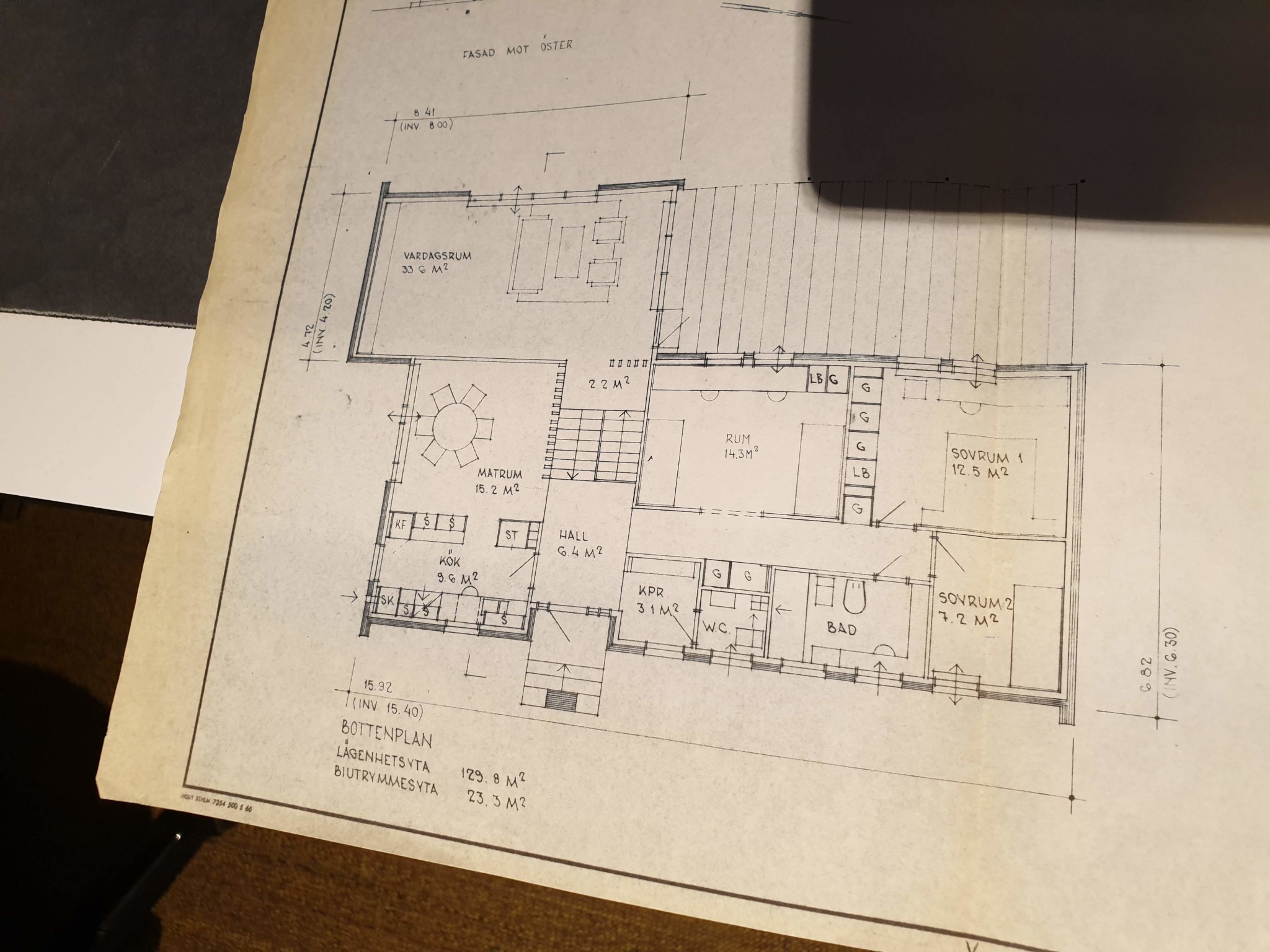
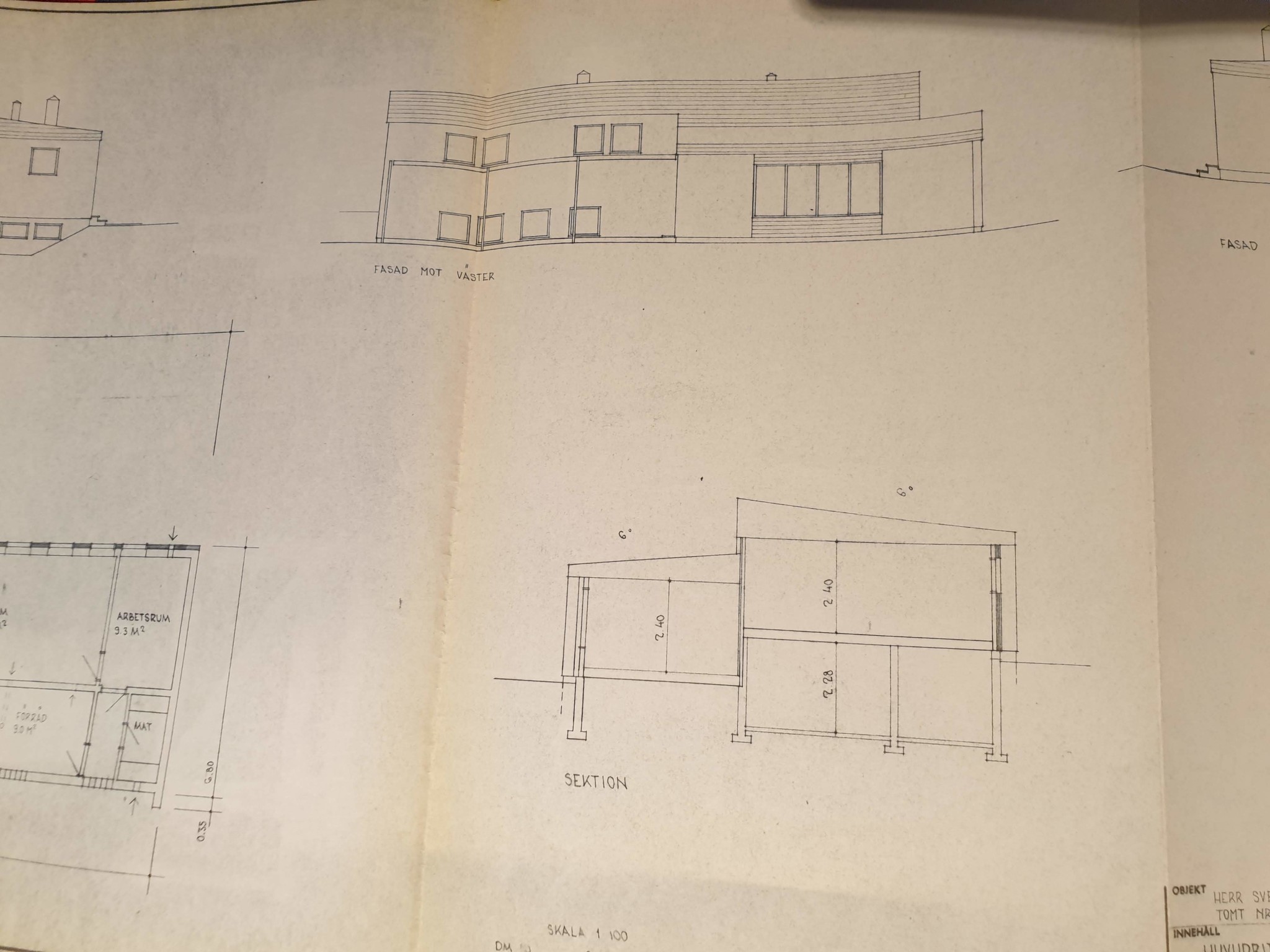
The necessary shifting of the wall inside is more complicated due to the fiber boards that are original to the design. It must be a Mockfjärdshus, right? The fiber boards need to be replaced by a beam whose dimensions primarily depend on how the roof trusses align with the window openings. Floor plans and information on the snow load zone are required to calculate the size of the relevant point loads. A sectional drawing always facilitates orientation.
The facade brick (which is not brick but limestone) does not take up any loads other than its own weight. The usual method is to use a brick beam that basically consists of two courses with intermediate reinforcement. Hire a mason for this.
The necessary replacement of the inner wall is more complicated due to the fiberplank in the original construction. It must be a Mockfjärdshus? The fiberplank must be replaced by a beam whose dimensions primarily depend on how the rafters align with the window openings. Floor plans and information about the snow load zone are needed to calculate the size of the point loads involved. A sectional drawing always facilitates orientation.
I'm aware that the brick is non-load bearing. According to the building descriptions of the house that we have kept, there should be reinforcement embedded in the two courses just above the windows.
Yes, there is fiberplank in the wall. And the house is from Hultsfredshus. The rafters with c-c 900mm align roughly with the division of the window, but do you need to worry about that if you insert a substantial horizontal beam that is 2m long? Then, in the worst-case scenario, you can calculate that a rafter ends up 1m from the support point, right? The house is located in the Jönköping area and has a low-pitched roof of 6 degrees (felt).
One does not always need to know exactly how things look. The worst-case load scenario that a 2 m beam can encounter with 900 mm c/c between the trusses is a truss precisely in the middle and two trusses each located 100 mm from the endpoints. With the information about the width of the house, one can easily calculate the point load that each truss can maximally represent. It is not necessary to know the roof construction either, as one can assume that all roof load falls on the outer walls. This results in an overestimation, but the consequences do not need to be too dramatic. What is missing now is the information about the width of the house.
You don't always need to know exactly how things look. The worst load case that a 2 m beam can encounter with 900 mm c/c between the trusses is a truss right in the middle and two trusses located 100 mm from the endpoints. With information about the house's width, you can easily calculate the point load that each truss can maximally represent. You don't need to know the roof design either but can assume that all roof load lands on the outer walls. It will be an overestimation, but the consequences don't need to be too dramatic. What is missing now is information about the house's width.
The house is 6.8m wide (the span of the trusses, that is), and I am highly doubtful if the interior walls in the middle of the house are load-bearing in any way. It is the upper row of windows in the "Facade facing west" that is to be remodeled. The trusses' position can be seen in the facade photo, you can see the nail rows on the facade (or the screws' position on the ridge plate).
Go with the suggestion above about the brick beam from Murma! Very good and stylish, I've used it myself in a couple of places.
Ok, but it's "only" a regular sheet metal cut like a ladder, right? I'm guessing we already have rebar embedded in two of the layers above the windows, my hope is that this will hold without needing to resort to masonry work. Is that a lie?
If we calculate slightly on the higher side, each truss represents a point load of about 11 kN. With the assumption that the middle truss is positioned in the center of the beam (which it is not according to the photo above), a 45x220 C 24 joist should suffice as a beam.
The next step is to see if the studs or elements that will support the beam can handle the vertical loads that occur. This involves 16.5 kN (≈1650 kg) per side according to the above calculations. This can be a lot for a slender and long stud. I'm unclear on how you have envisioned the solution.
The next step is to see if the studs or elements that are to support the beam can handle the vertical loads that arise. It is about 16.5 kN (≈1650 kg) per side according to the above calculation. This might be a lot for a slender and long stud. I'm unclear on how you've planned the solution.
Can one suspect that the load of the two studs is taken up by two others directly below that are then flush with the window below?
What do the studs to the left of the window look like? Or is there only one?