Hehe, ok, that sounds good! Take a classic Swedish roof truss as an example instead, where the floor structure is built separately but is still part of the roof trusses
If the joist is just a joist, you can divide it into two parts where each part has sufficient bending stiffness independently of each other, with, for example, a steel beam in the middle with beams inserted from each direction.
If the joist is also part of the truss construction (as for gabbe1, #4) it seems unsuitable for the joist to be two separate parts that do not interact. Then I agree that the joint should not be made in the middle but instead go with TS's suggestion.
Do my theories hold up?
Not in practice, in my case.
The trusses were delivered with split bottom chords and intermediate beams for a five-meter width.
The function of the bottom chord, apart from serving as a base for the attic floor, is just to absorb tensile loads, so the outer walls are not pushed outwards by the weight of the roof.
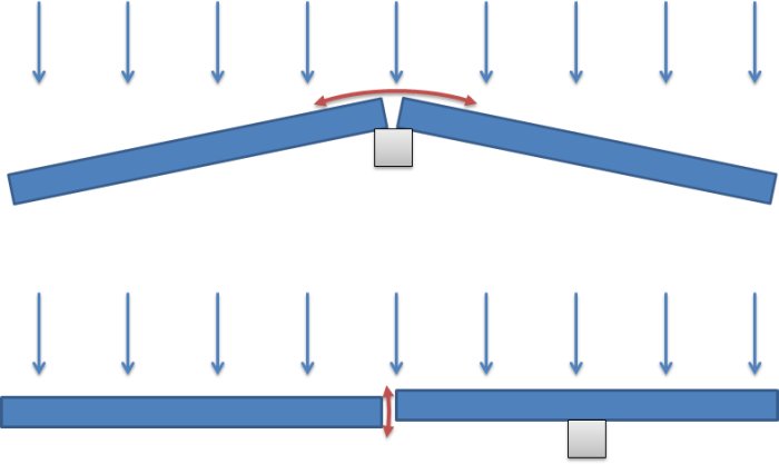
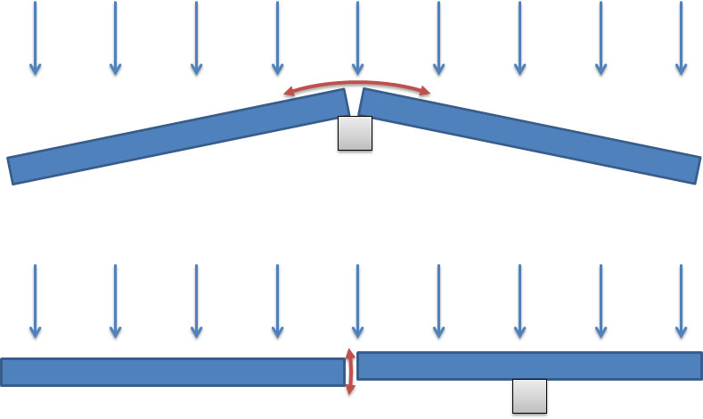
If you splice AT the center support, the splice becomes moment-free. I would never do it like in the first picture. It won't work.
If you have to splice, splice near a support and stagger the joists, not end to end.
Splicing with 50cm laps of the timber probably works just as well as the nail plate. But if you can stagger them, it will be stronger. It doesn't matter to shift the joist 5cm on one half, does it?
Having the beam under the joists can be an advantage if you want to make room for things like ventilation and drainage.
Search for spikningsplåt, which is the correct term. Here http://www.traguiden.se/TGtemplates/popup1spalt.aspx?id=824 you have some info on how to nail, the principle is to nail as much as possible. Spikningsplåt is primarily used to absorb tensile forces and you get a significantly stiffer beam by screwing/gluing a joist alongside as several have suggested.
I would have gone with kertubalkar, they are absolutely superb for this type of problem.
Hmm.. ok.
JO, this is not the perfect choice of solution to the problem, but it partly depends on the current conditions. The beams already exist, so it's good if they can be utilized.
In your sketch, you have drawn that the beams are longer than half the width of the floor structure, therefore you have placed the joints staggered, and in different directions in every other course.
But, do you have enough studs so that you can place two studs next to each other and overlap the joints?
Mikael_L, a screw joint you have designed will be really strong and will suffice every time. But if I remember correctly from school, the tensile forces are greatest just over the steel beam, and therefore the joints should be a bit away (1/4-1/3 of the length). At least if I may discuss the theory
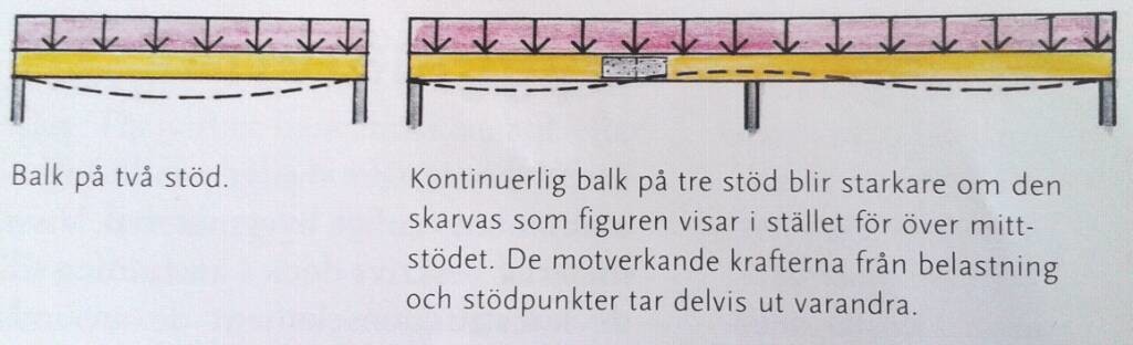
In the example above, you have a "breaking" force over the steel beam, but a vertical force if the joint is free. The breaking force will be significantly larger and is harder to secure, even with screw joints. That is probably why the book "Husets ABC" also recommends the other option (see my post #18 http://www.byggahus.se/forum/byggma...alklag-50x200-med-spikplatar.html#post1799002)
I would never use sheet metal, I would never risk getting creaks or other noise from a sheet rubbing against wood because you can't get metal against wood completely silent. Wood moves.
It's gluing that matters to me.
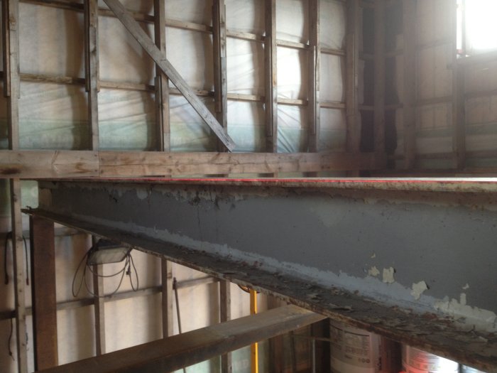
Then I wonder what kind of construction it is, the studs are 50 x 200, not 45x195, and all the wood is gray. Long-term project?
Protte
Vi vill skicka notiser för ämnen du bevakar och händelser som berör dig.


")