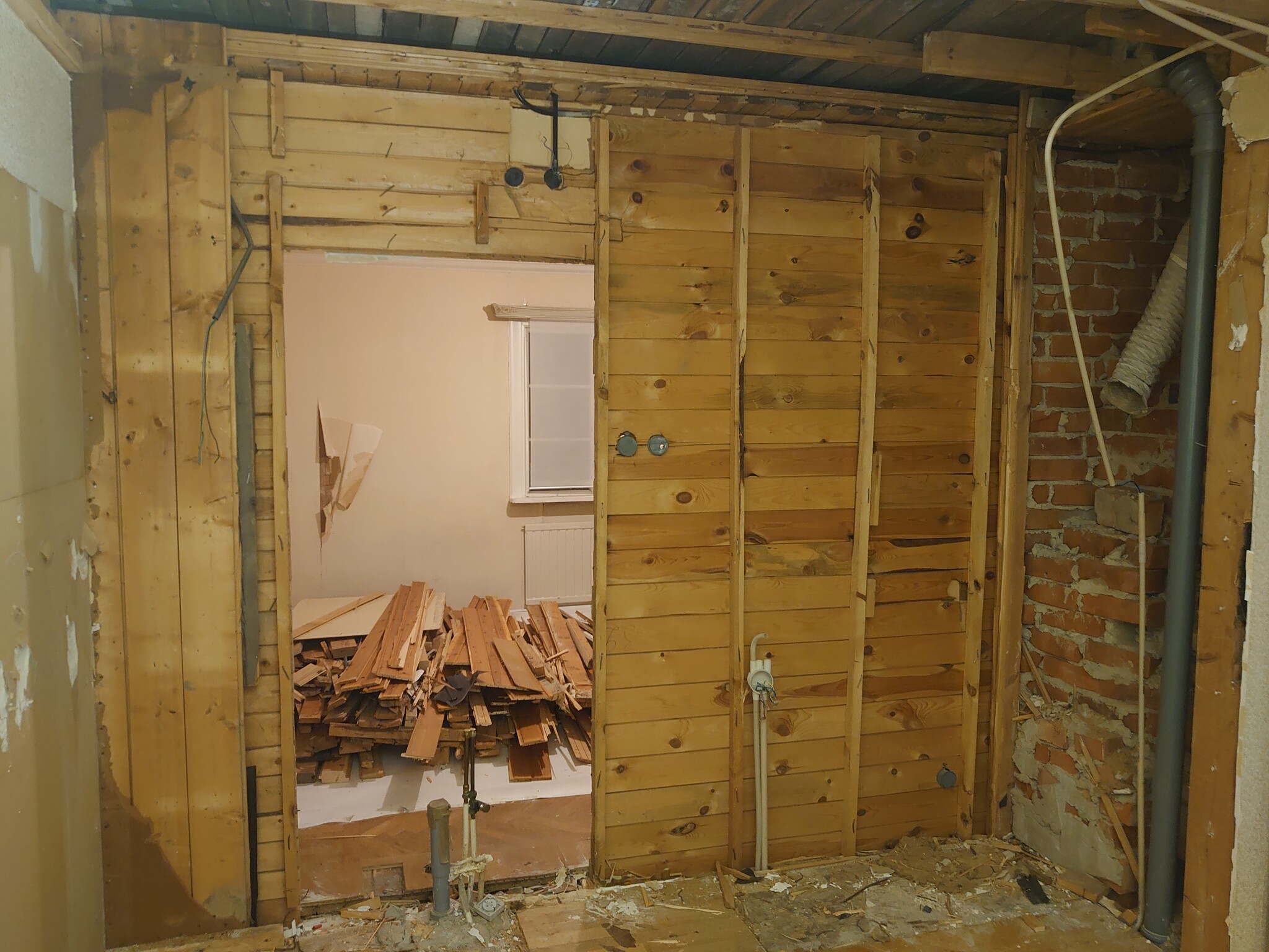
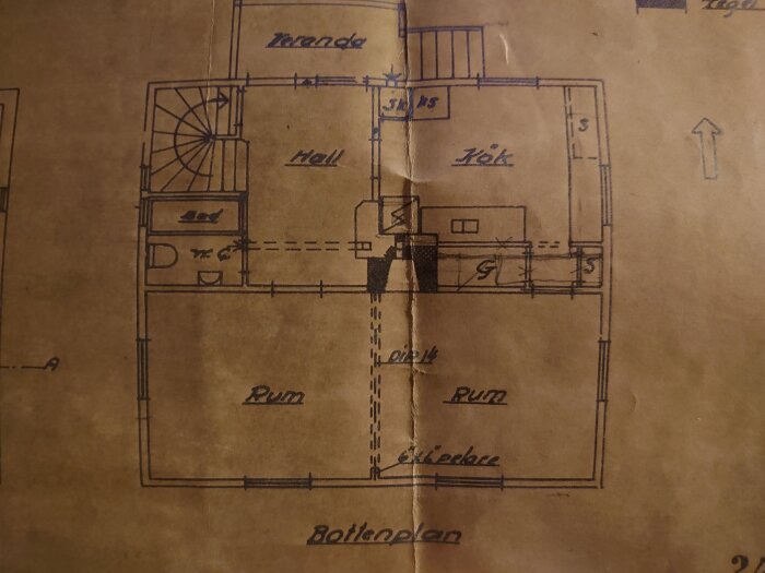
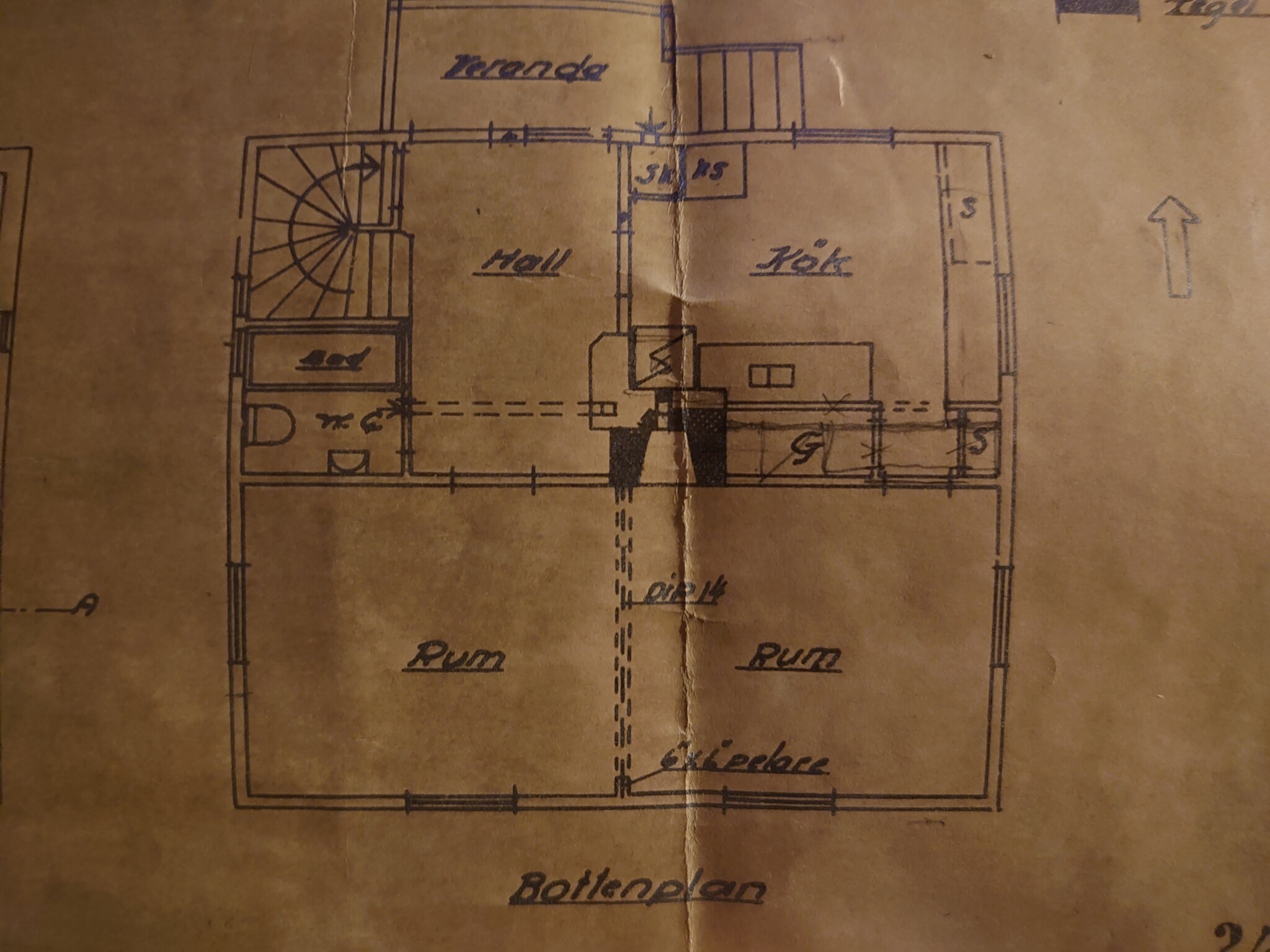
We would like to open up the wall from the kitchen to the living room. Today it has been completely closed; I saw on the old drawings that there used to be a door between the kitchen and the living room. I have also located a steel beam that looks like an H-profile resting on a ledge on the chimney and running out to the wall (see dashed line in the living room), on the drawing it says DIP14 on the beam, I don't know what it stands for?
Do we need to unload the wall between the kitchen/living room or is it sufficient?
The house has a basement, and 2 floors plus an attic.
Since it looks like a house built before the 50s, one cannot be sure what are load-bearing and stabilizing walls. To determine if a wall is load-bearing, it usually works to open up the floor from either side and see if the joists rest on the wall or run along the wall. There is also a stabilizing effect with a wall that ensures it remains 90 degrees between the floor and the outer wall so that the outer wall does not buckle outward.
You should hire a structural engineer who can come out and see how it is built.
DIP was a type of beam (presumably an H-beam) and 14 probably stands for the dimension.
Since it looks like a house built before the '50s, you can't be sure what are load-bearing and stabilizing walls. To determine if a wall is load-bearing, it usually works to open up the flooring from either side and see if the beams rest on the wall or run along the wall. There is also a stabilizing effect with a wall that ensures a 90-degree angle between the flooring and the outer wall so that the outer wall doesn't topple outward.
You should hire a structural engineer who can come out and see how it is constructed.
DIP was a type of beam (probably an H-beam) and 14 likely represents the dimension.
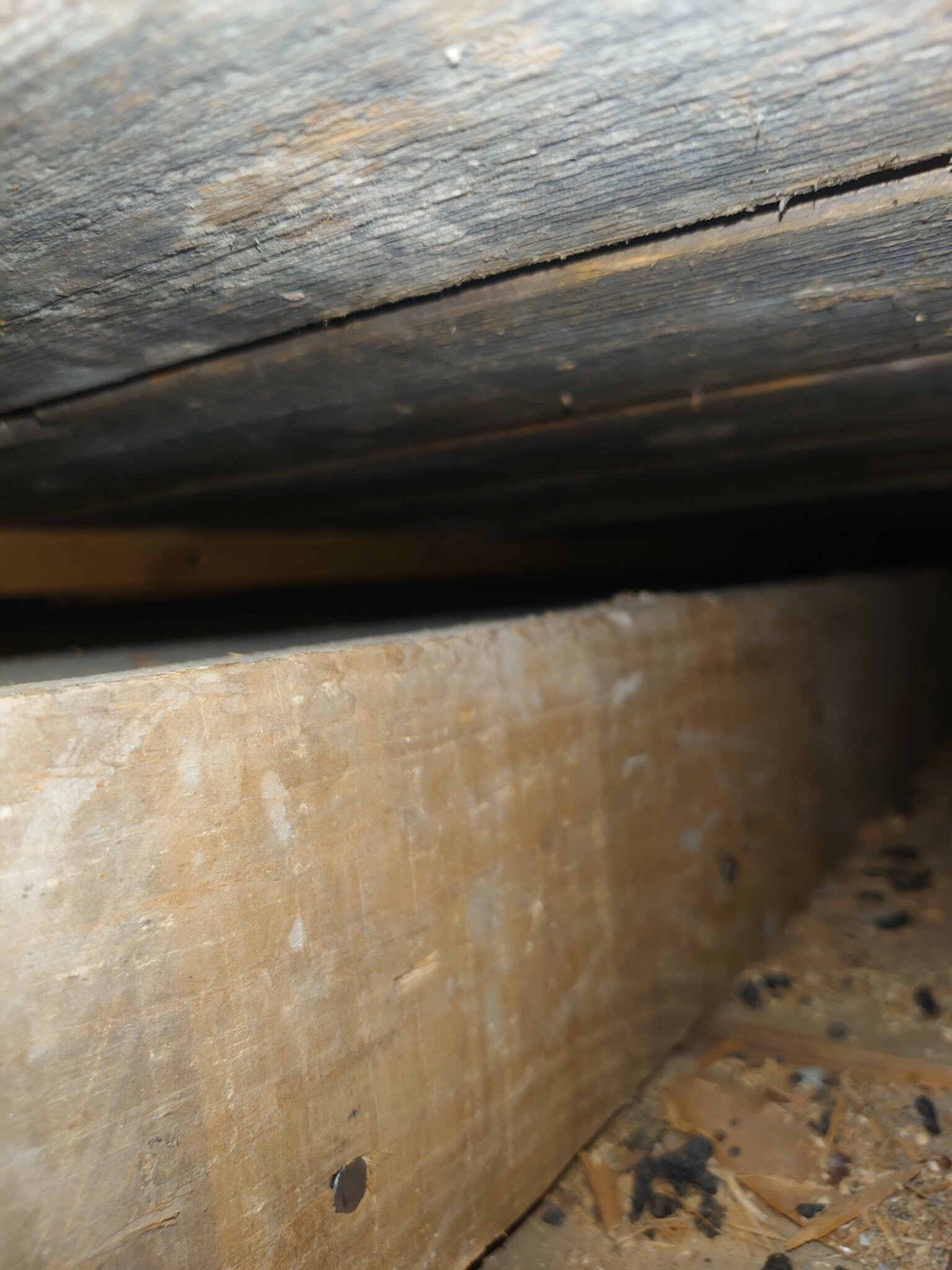
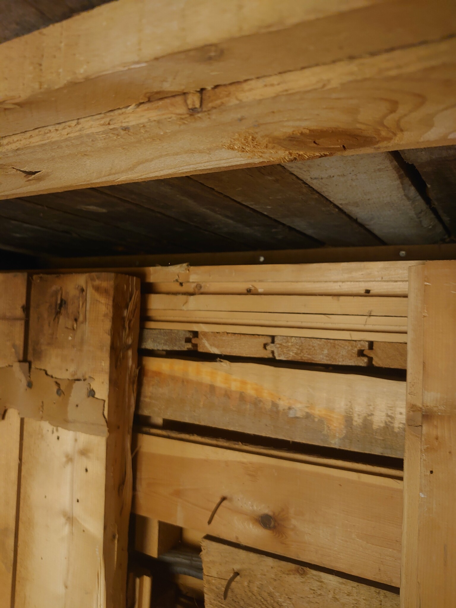
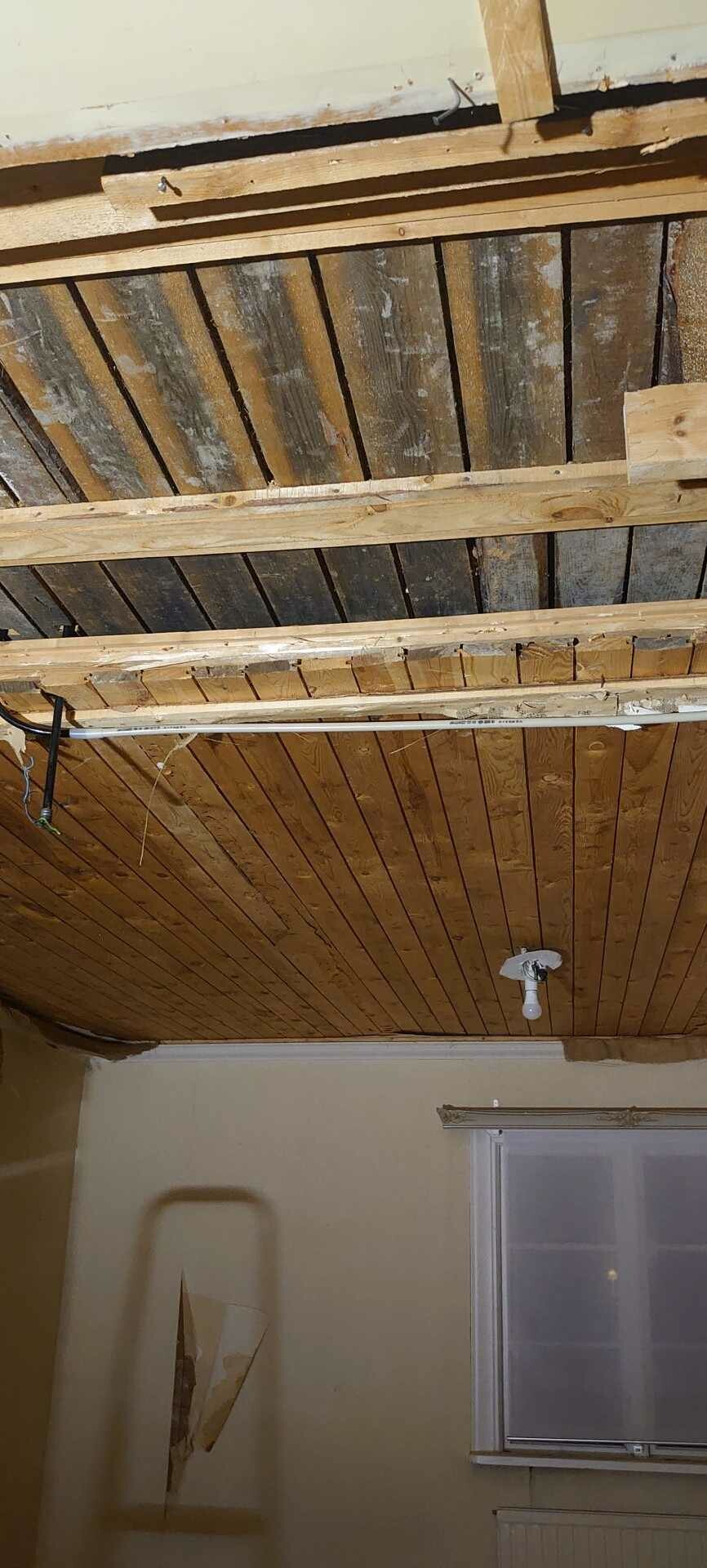
I made a small hole in the kitchen ceiling and managed to take some pictures. What it looks like is the wall is not load-bearing since there is a gap between the stud and the floor above. However, there was a wooden brace in the corner that seems to have some load-bearing function?
Was downstairs and tore down the ceiling, so now you can quite clearly see that the standing planks/wall and the beam behind that the planks are nailed into do not lie flush against the above ceiling/beam.
It looks good, but you should probably make sure that the transverse beam, which currently has support on top of the wall, also gets some sort of support in the future. I mean the one seen in the last picture.
It looks good, but you should probably make sure that the crossbeam that now has support on top of the wall gets some sort of support in the future as well. That's the one seen in the last picture.
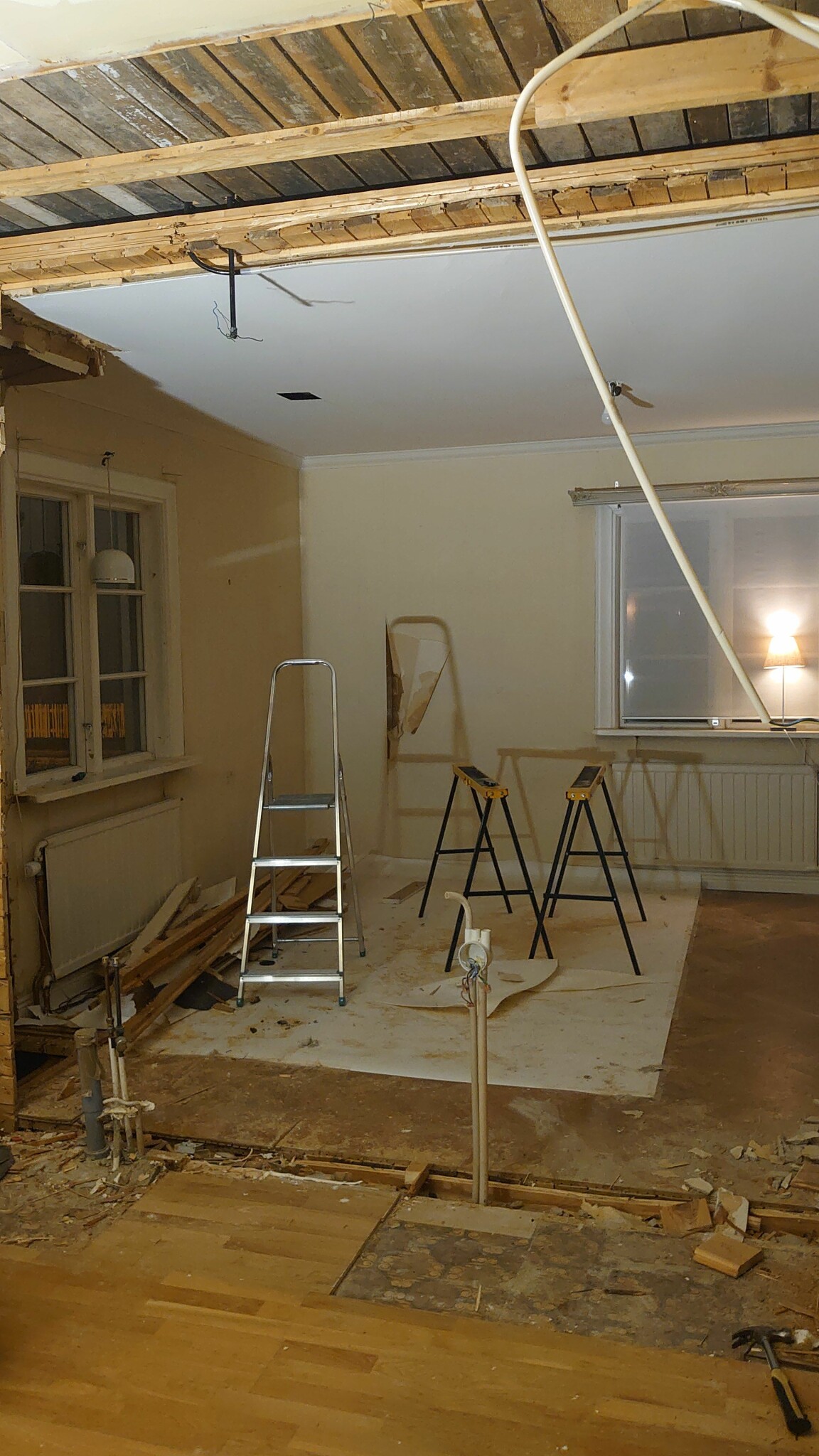
Yes, we will leave it for now. Have taken down the other wall. Also tore down the tension paper in the living room.
Just noticed that there's about 11 cm from the ceiling to the floor joist
Got a bit tempted to saw down all the planks in the ceiling. It should be okay to put up new framing against the floor joist (and also have the opportunity to level the ceiling), but also have the possibility to run new wiring and even gain a bit of height, around 4-5 cm?
Click here to reply
Vi vill skicka notiser för ämnen du bevakar och händelser som berör dig.


BirgitS said:
Since it looks like a house built before the '50s, you can't be sure what are load-bearing and stabilizing walls. To determine if a wall is load-bearing, it usually works to open up the flooring from either side and see if the beams rest on the wall or run along the wall. There is also a stabilizing effect with a wall that ensures a 90-degree angle between the flooring and the outer wall so that the outer wall doesn't topple outward.