Heavily discussed, I know, but it doesn't help because I haven't found any answers on how to do it 😅
I could use some help understanding how to construct a beam support.
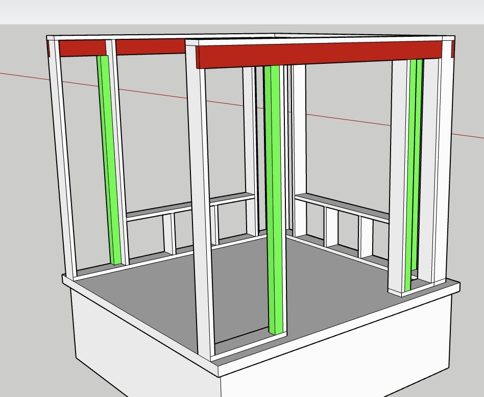
I have a small addition planned, about 3x3m, where there will be a broken insulated sheet metal roof with about a 20-degree slope and rafters along each wall. In the addition, there will be a double door about 160cm wide, as well as large "floor-to-ceiling" window sections about 180x180cm. I planned for the wall to be built primarily with 45x195.
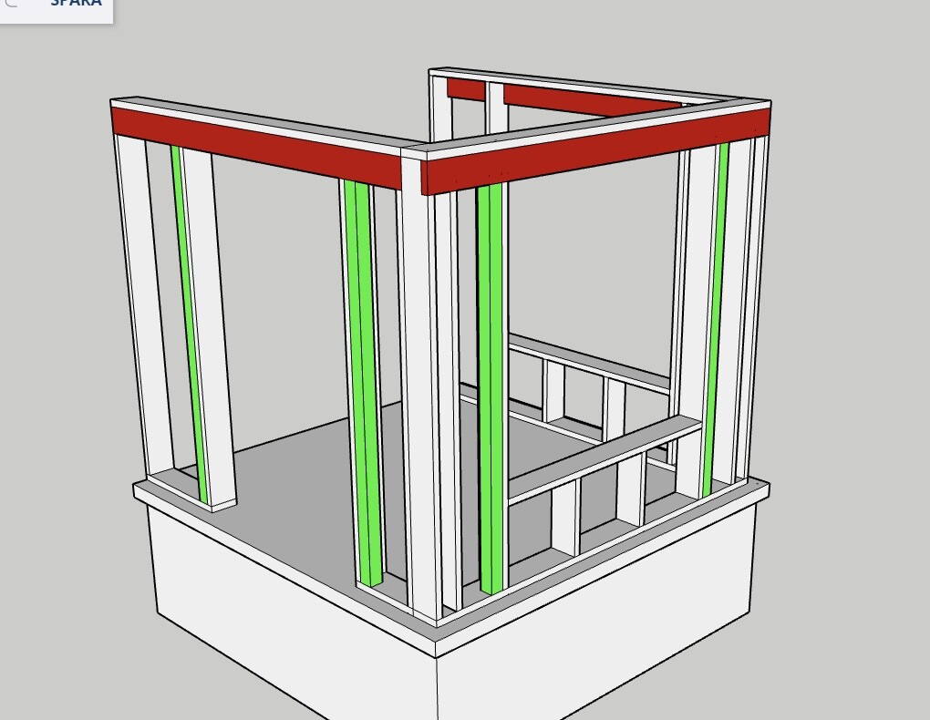
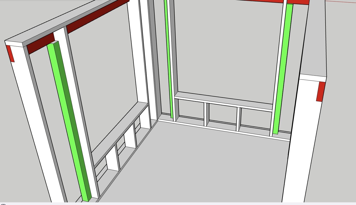
Initially, I didn't think much about beam support, but now I'm in the thick of it and have calculated using a dimensioning program that, for example, 45x170 as a beam (red) and 90x90 glulam (green) as a side beam.
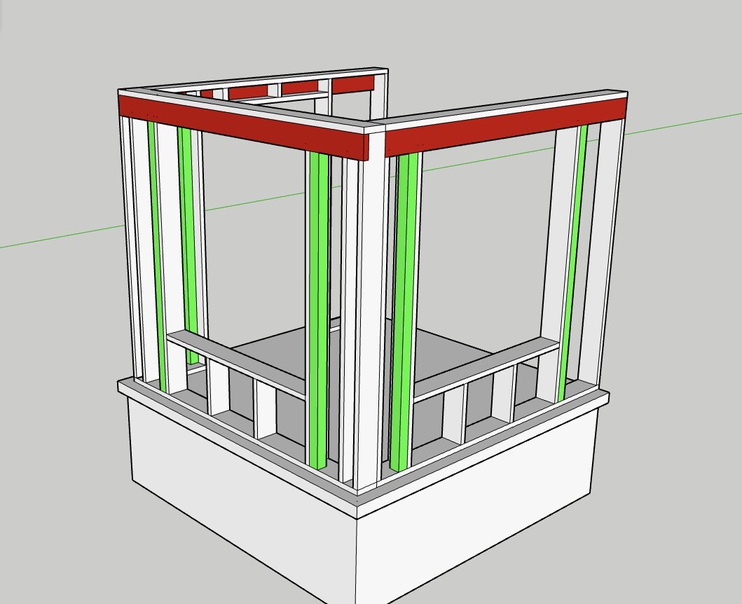
I assume there are a thousand different ways to build these; can anyone say if my drawings are one of these thousand alternatives? 😅 Or have I got it all completely wrong?
Suggestions for another construction? Cheaper? More convenient? More efficient? It feels off the top of my head like such short distances that a standing post in each outer corner with a wall plate and a supporting beam from the facade would have been enough, then just frame around it to get the desired wall thickness and attachment points for panel and facade material. But how do you usually do it??
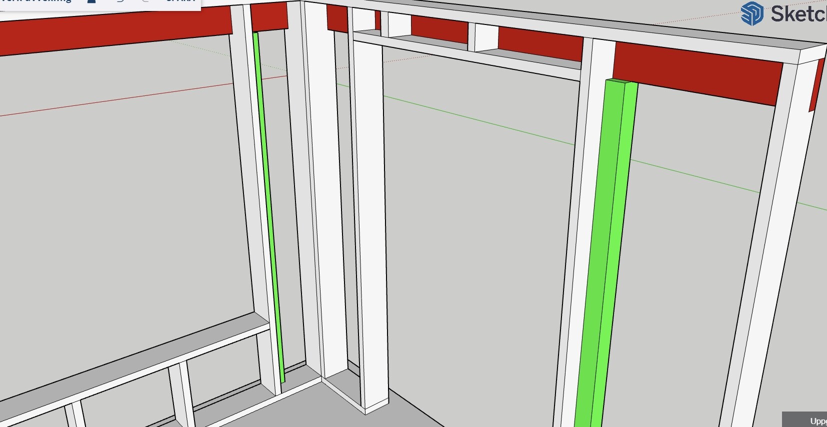
By the way, how do you do the top of the windows? I've been forced to have the standing 170 level (the wall plate? Support Beam? The green one...) at that level to make the windows and roof nicely align with the rest of the house, but then I have no support at the back of the frame. Do you put a horizontal 145 beam at the same height as the standing 170, or do you split a 170 to exactly 150mm to fit?