Can you see the balcony's construction from underneath? If so, take a photo that shows the short side of the balcony that also rests on the post.
I've requested drawings from the board and may possibly get to see a neighbor's drawing, though he has only extended straight out, not sideways as we desire.
Some photos:
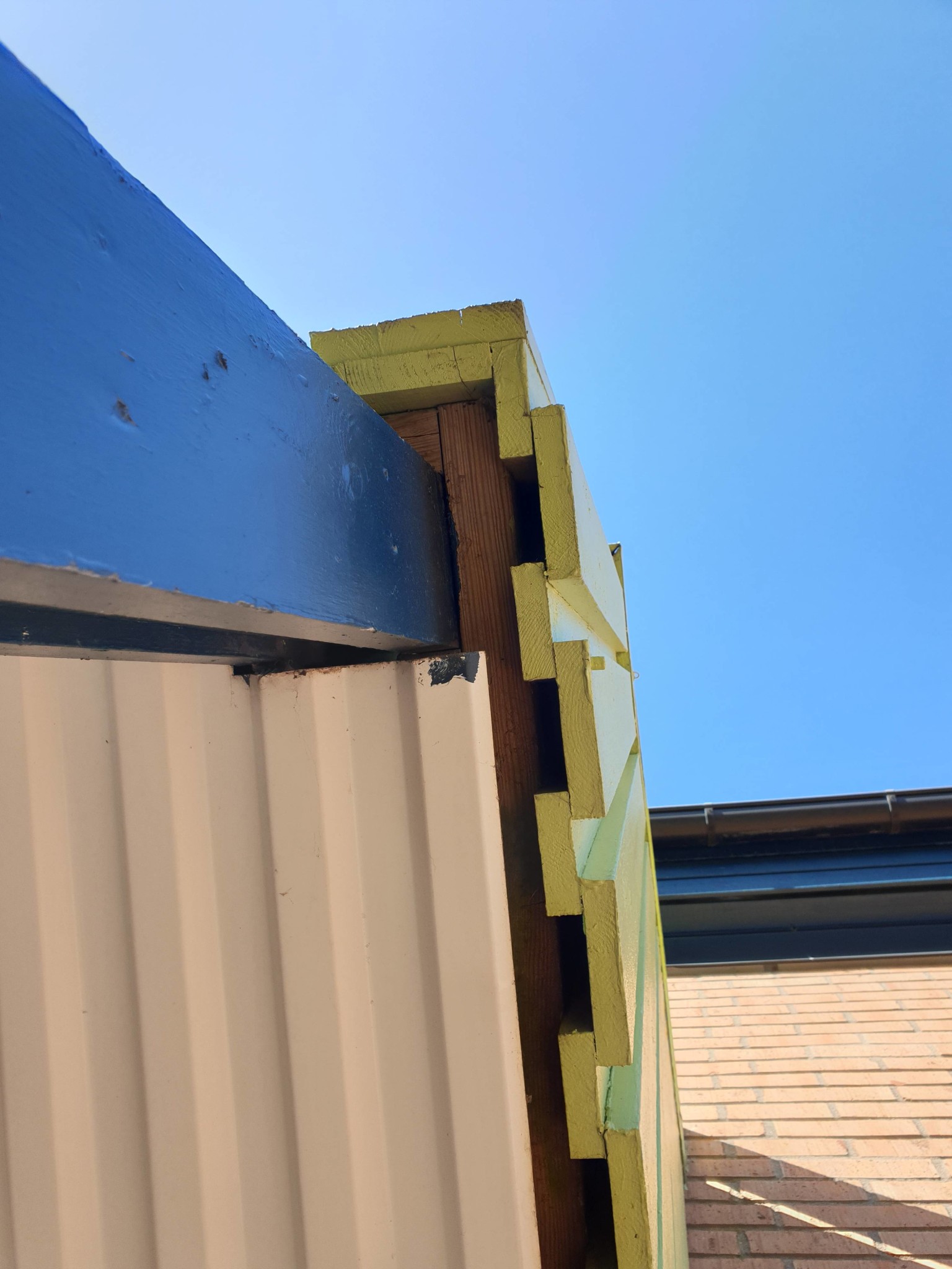
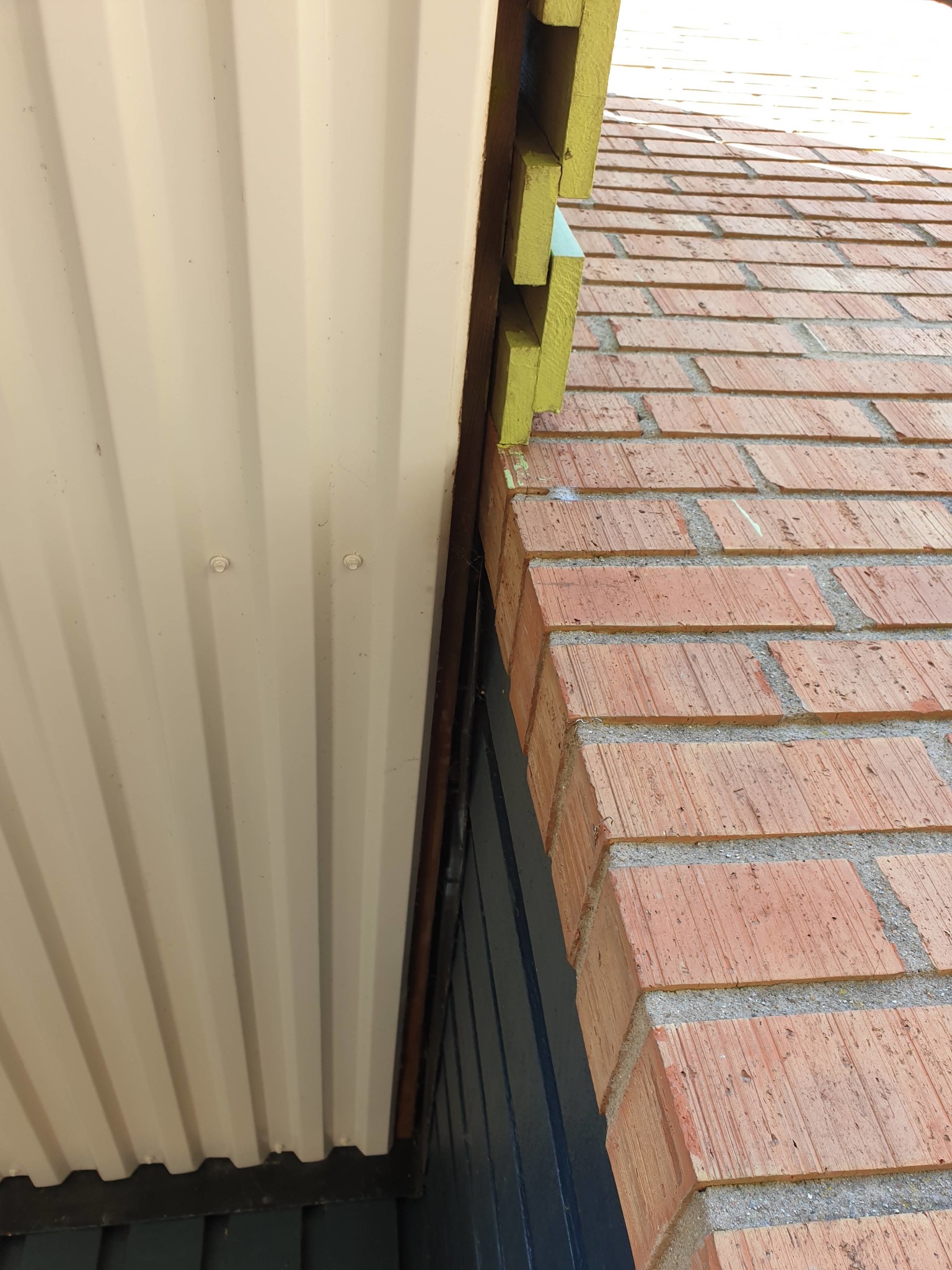
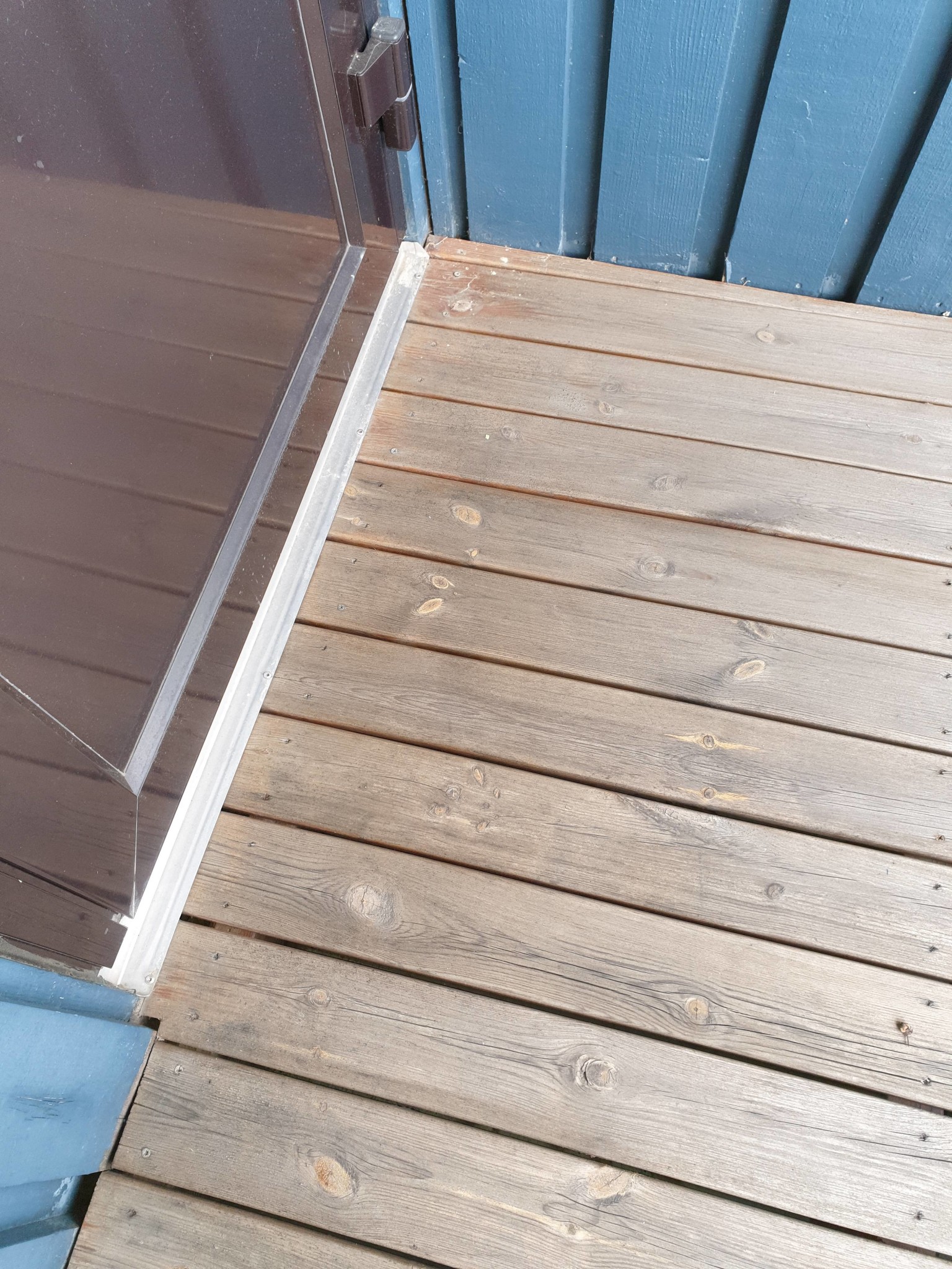
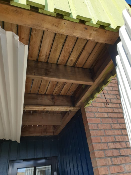
1-2-3-4 the short side that goes from post to house wall above the patio door.
5-6 the opposite short side
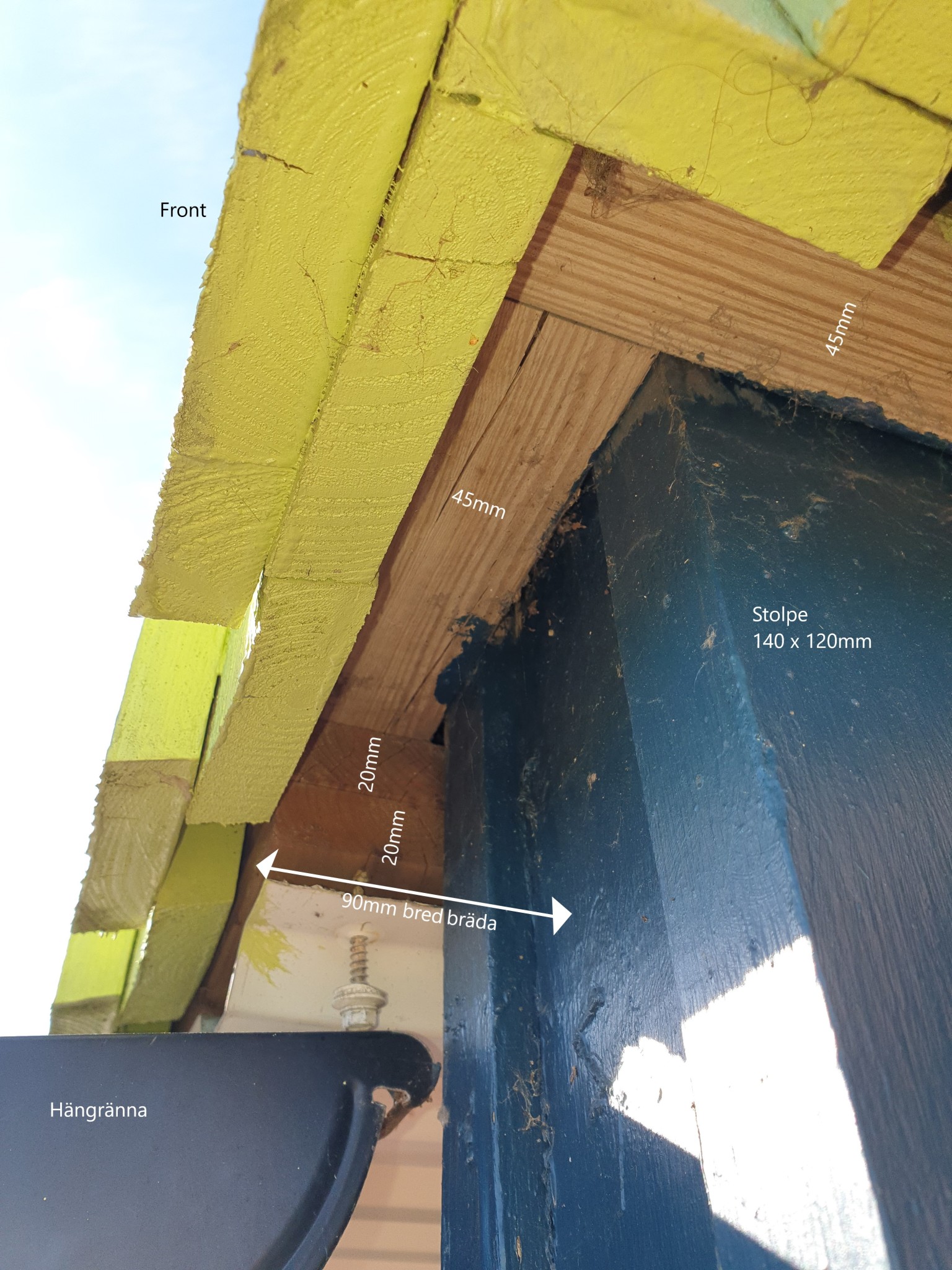
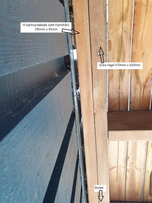
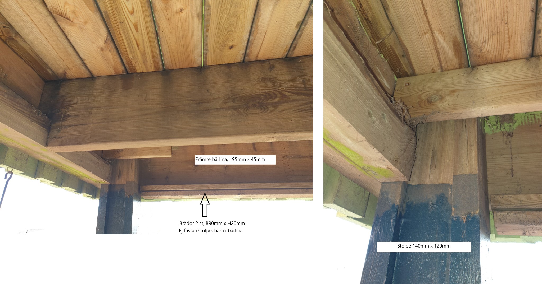
7 detail + measurements at the post
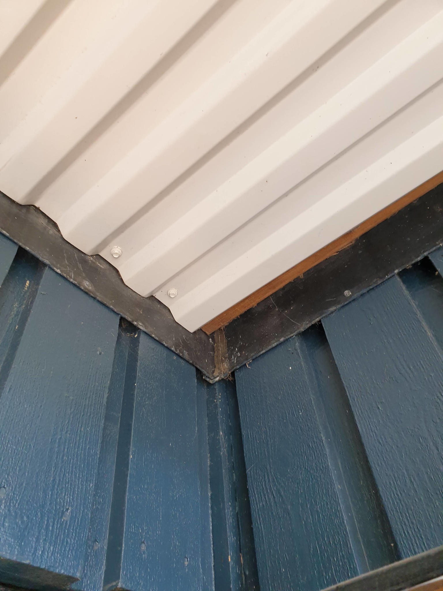
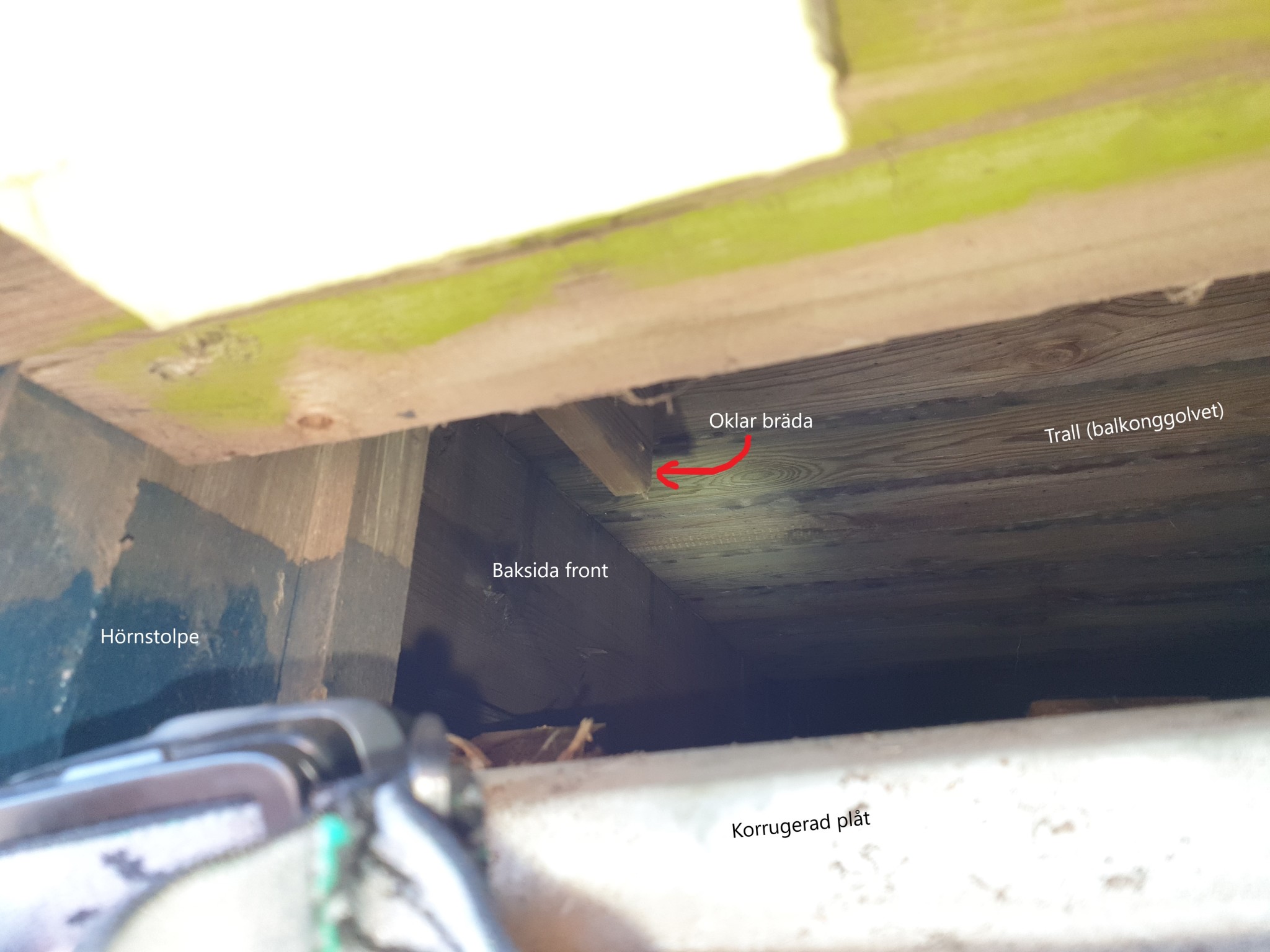
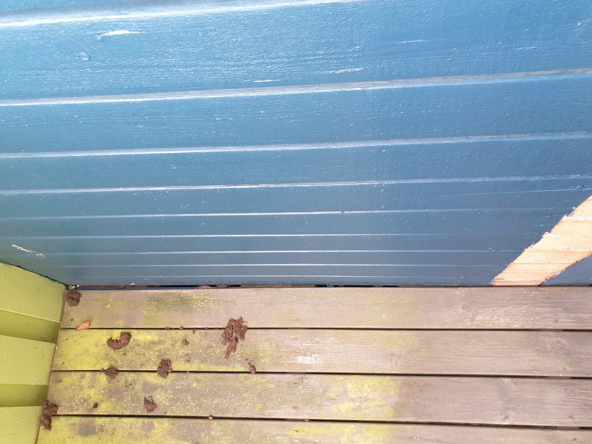
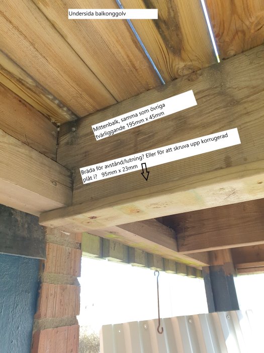
8-9 from underneath, between the sheet metal and balcony floor.
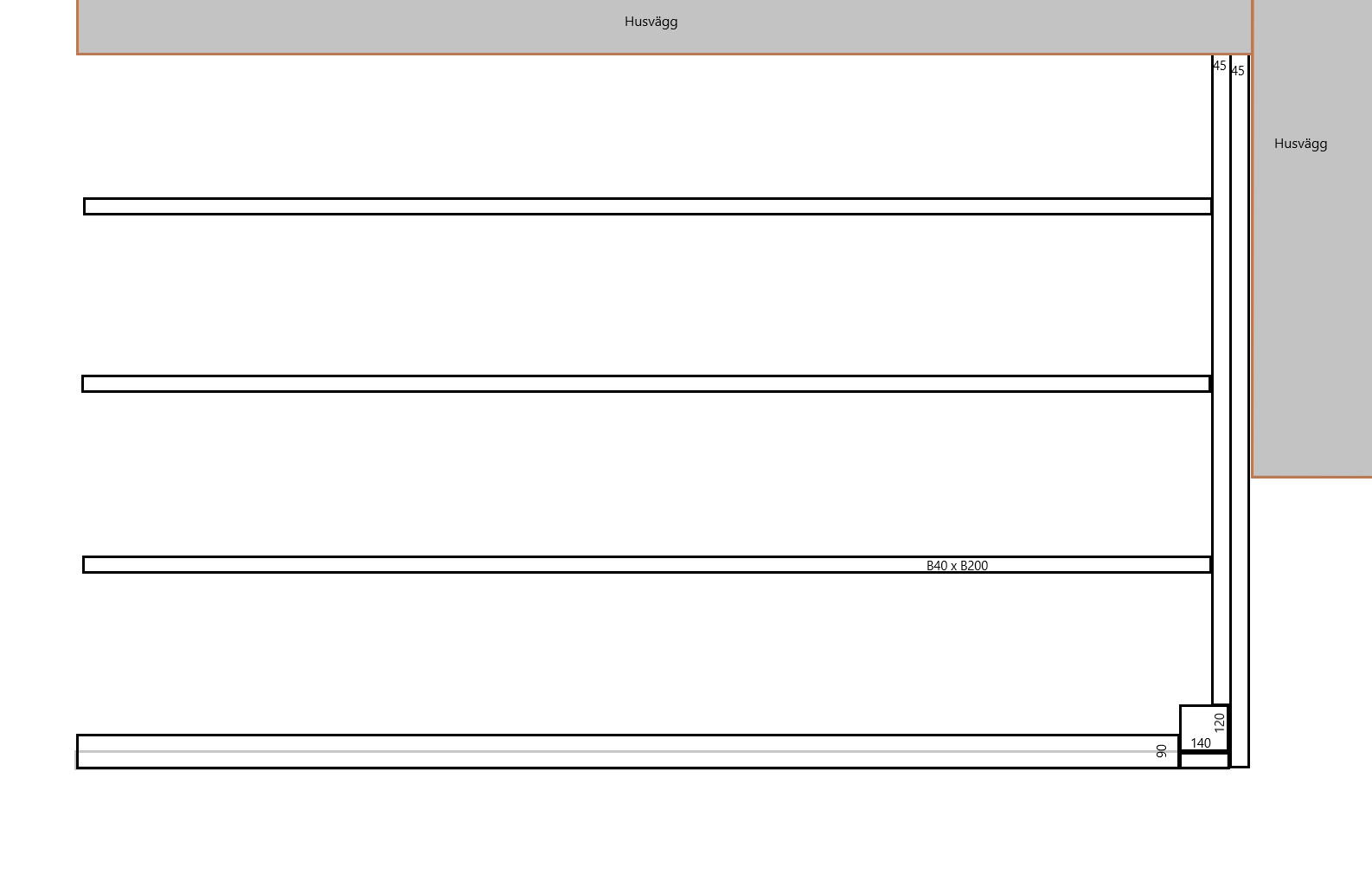
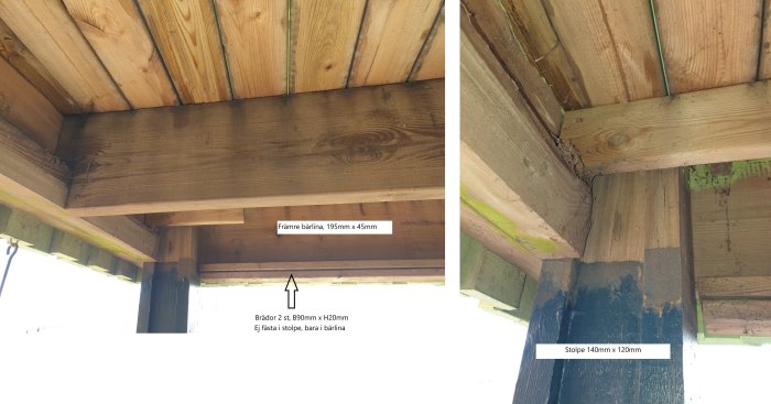
10 a simple sketch of what I've managed to measure. The front of the balcony is thus supported by both a cross-rail/beam of 45mm but below it also 2 boards that are 2mm thick and 9cm wide. It wasn't so easy to draw in.
The cross beams are 3 in total plus the beam at the house wall and the terminating beam at the front.
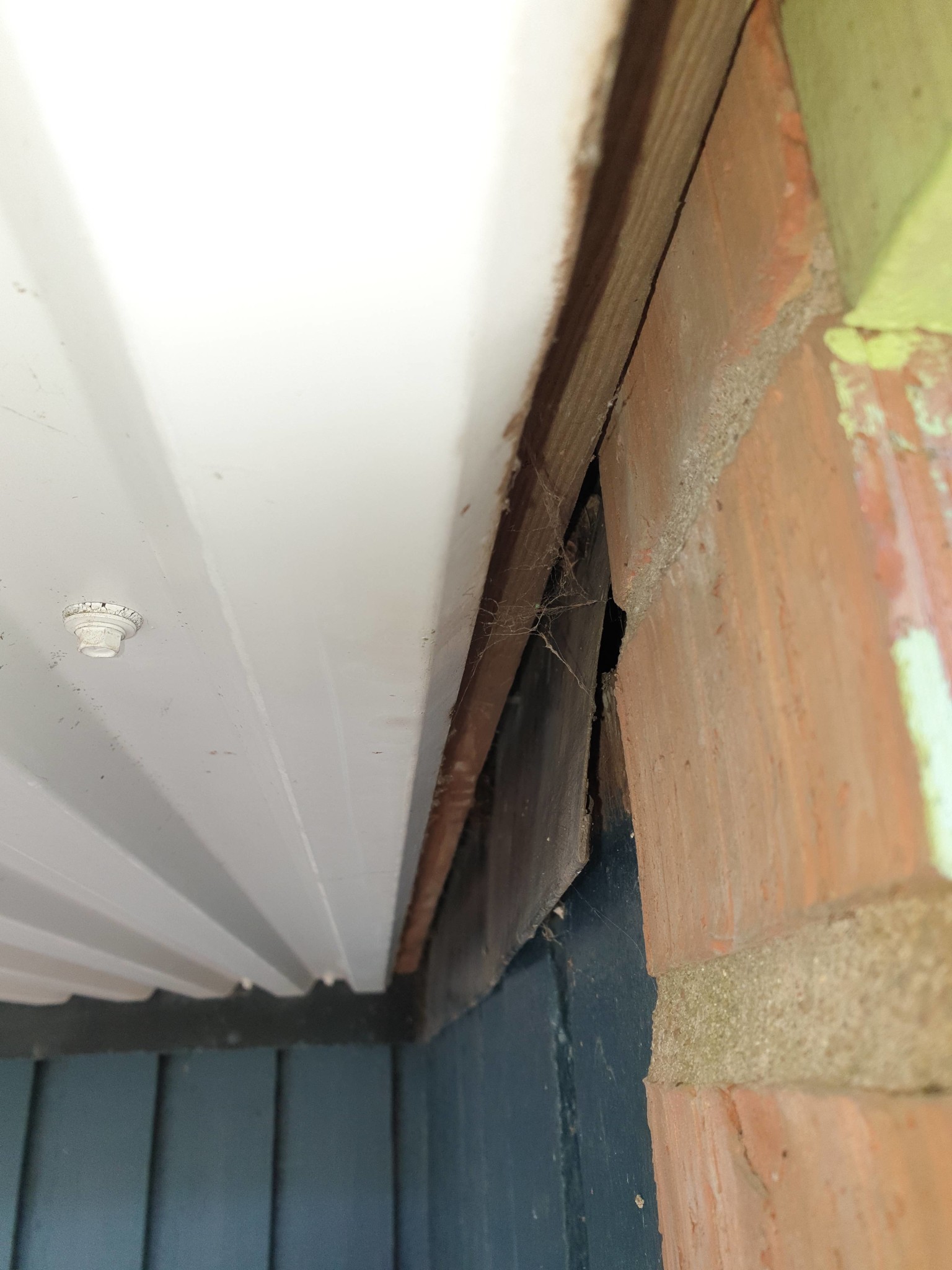
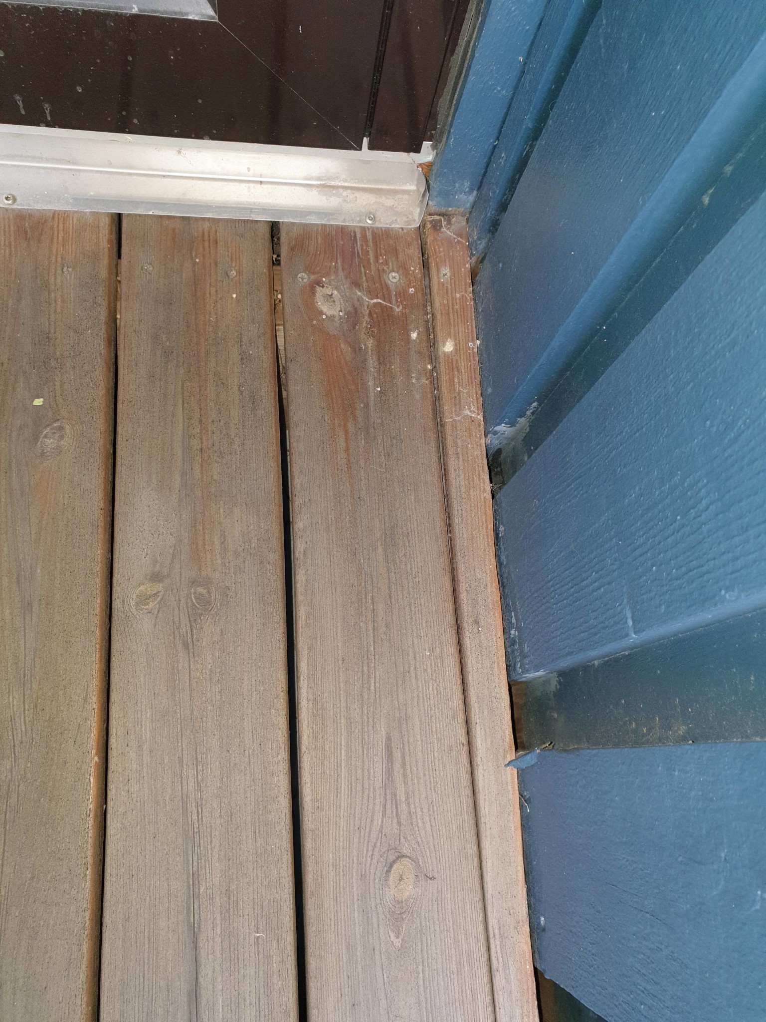
There is a sheet metal around the entire inner part of the balcony that sticks out on the underside (photo 3-4-5). I don't really understand its function.
I can't see with the naked eye how the beams are attached to the facade.
Some pictures from the top of the balcony as well
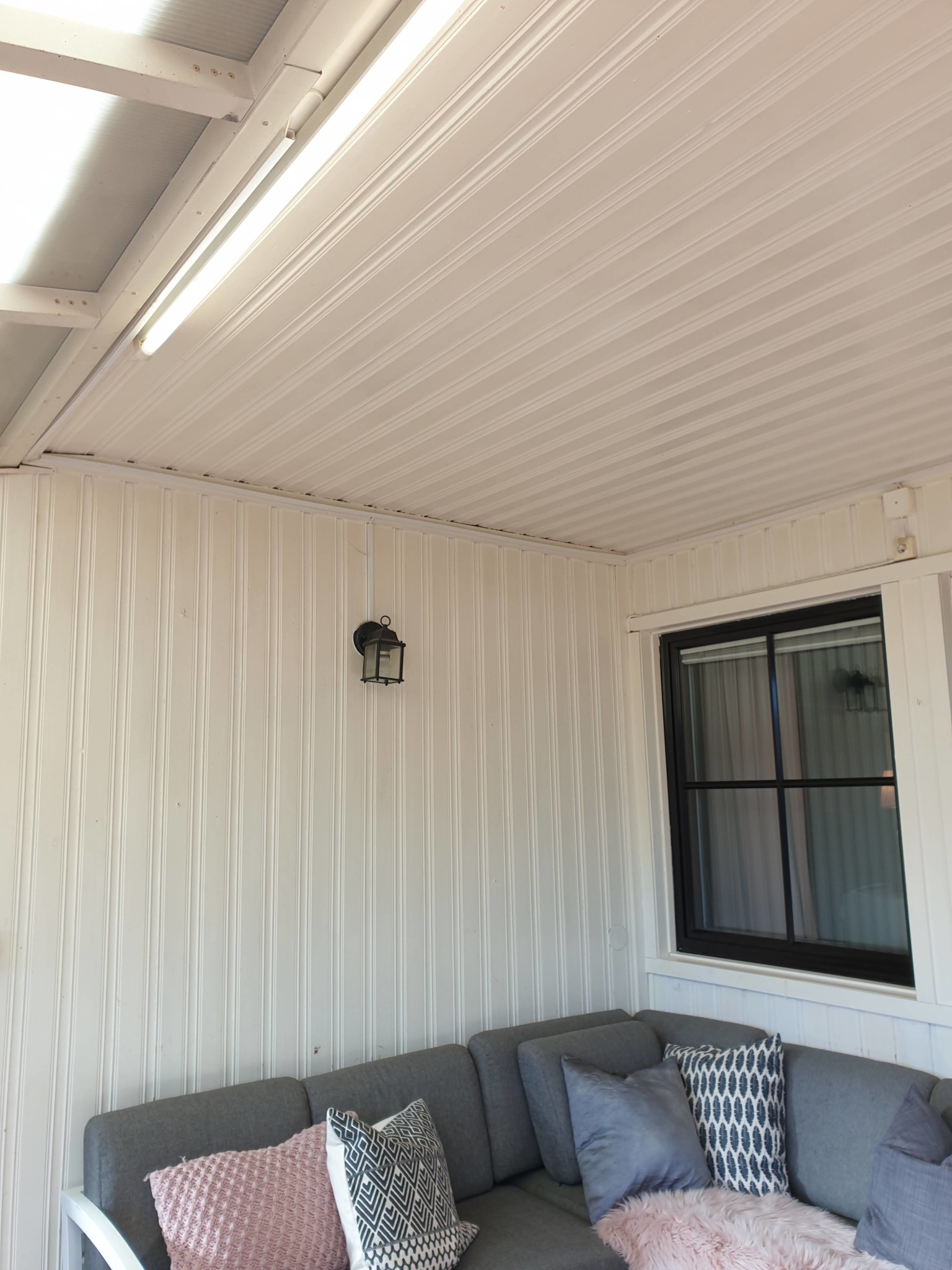
11-12 by the balcony door (directly above the patio door)
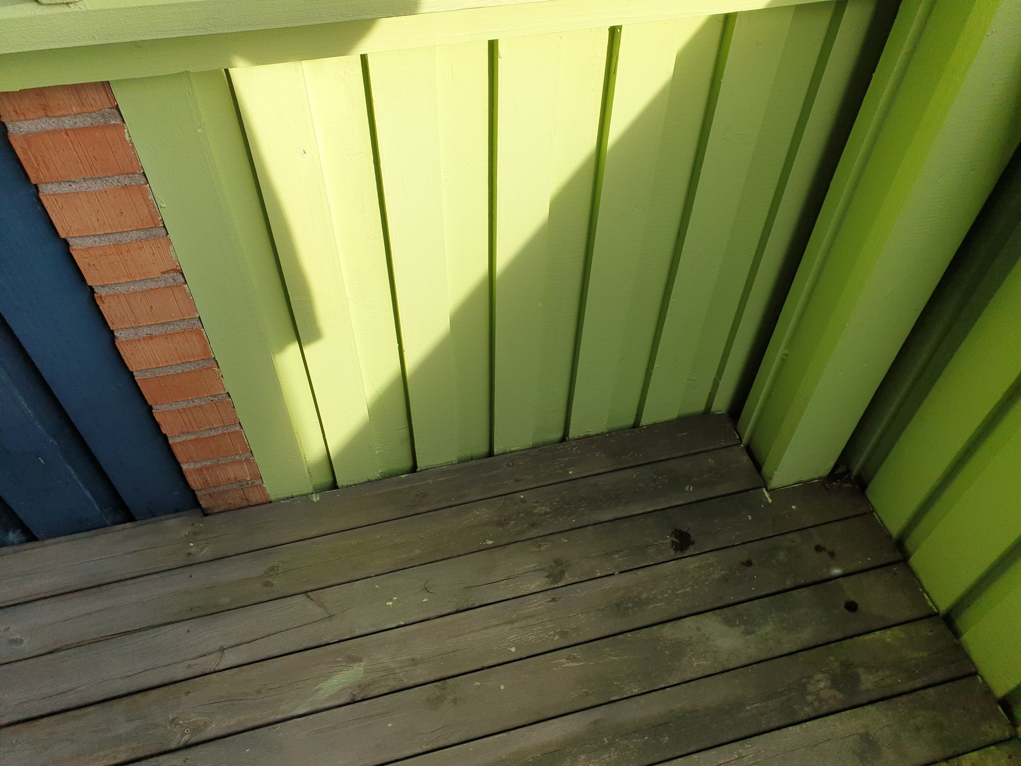
13 in the corner where the post supports
14 opposite corner where the wall supports
The post goes all the way up even above the balcony, meaning the weight cannot rest on the post, but the support beams must be anchored on the side of the post...
Feeling quite resigned, everything is at a standstill. I haven't heard from the structural engineer, nothing is happening with the 2 quotes I'm waiting for, and all I do is read page after page of information far beyond my level of building experience.
Right now there are 3 options:
1) We skip the sunroom but extend the wall on one side and replace it with a longer sheet so at least it won't rain under the balcony this summer. We build a new deck, and the stupid pole stays where it is and is in the way.
2) We get a design drawn up for a lot of money and can subcontract the critical parts of the construction (roof, supporting structure, footings), then spend the whole summer trying to finish it ourselves. Logically, I can follow a plan, but the most building experience I have is constructing a box house for the cat. So I want everything drawn and calculated, then preparations with getting the right tools and understanding what I'm doing.
3) I try to figure out how each part is done one by one and slowly do one part at a time. I'll be done in 10 years because I'm so damn meticulous.
As far as I can see, the post continues up to the height of the balcony railing. It therefore does not bear any other loads. I interpret your pictures as the beam supporting the right side (viewed from the outside) of the balcony resting on the post and the facade wall at the innermost point. Then, it can be calculated that the post load is approximately 4 kN (400 kg), which is not much. A new beam replacing the post and the existing beam should be able to rest on the beam meant to be above the sliding door section without having its own post. This beam can be made of glue-laminated timber with very moderate dimensions, e.g. 90x180 mm. When building the conservatory, the balcony must be supported temporarily while the post and existing beam are removed. The challenging part of this project is constructing a roof over the conservatory from below. Structurally, it is quite simple.
As far as I can see, the post continues up to the height of the balcony railing. It therefore doesn't bear any other loads. I interpret your photos as showing that the beam supporting the right side (viewed from the outside) of the balcony rests on the post and the facade wall at the far end. You can then calculate that the post load is about 4 kN (400 kg), which isn't too much. A new beam replacing the post and the existing beam should be able to rest on the beam above the sliding door section without having its own post. This beam can be made of glulam with very moderate dimensions, e.g., 90x180 mm. When you build the sunroom, the balcony must be propped up (get temporary support) while you remove the post and existing beam. The difficult part of this project is building a roof over the sunroom from below. The construction itself is fairly simple.
Thanks a lot for the answer. I didn't realize until I saw the pictures that the post actually goes all the way up to the railing and therefore can't possibly bear such a large part of the balcony's weight . Sometimes you don't think that far.
The offer from the structural engineer came yesterday at 26,000 + VAT so it's not happening right now. I'll continue researching myself and see if it's possible to lower the price by preparing more materials.
But - the load-bearing capacity of the frame shouldn't be too difficult to achieve.
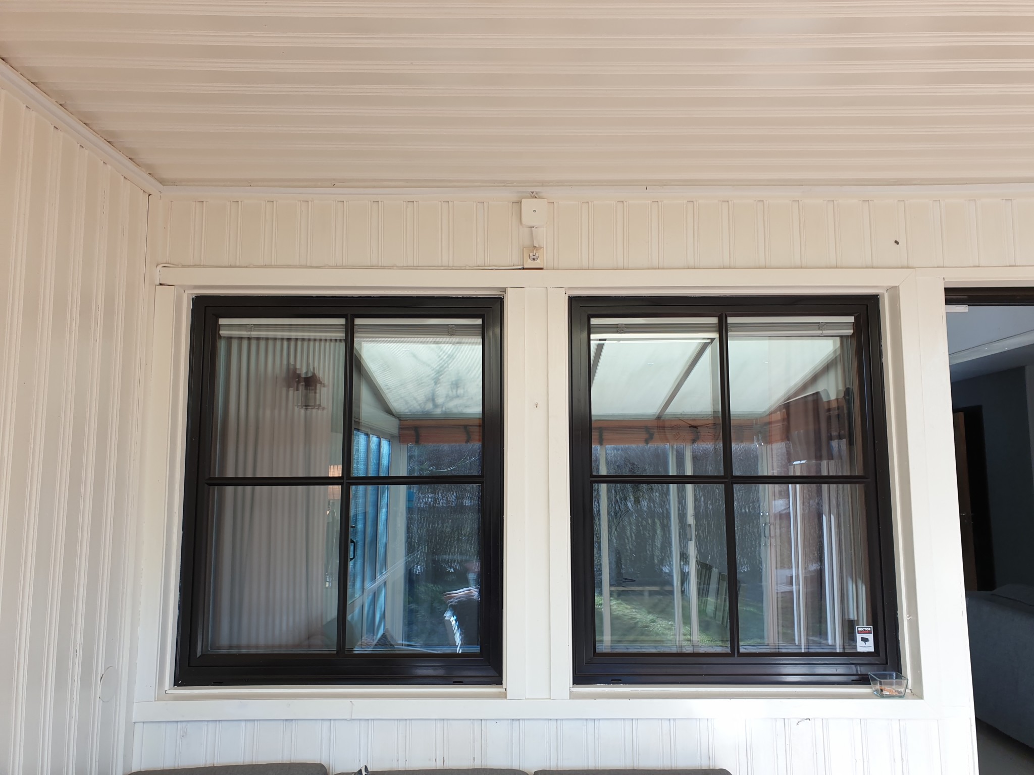
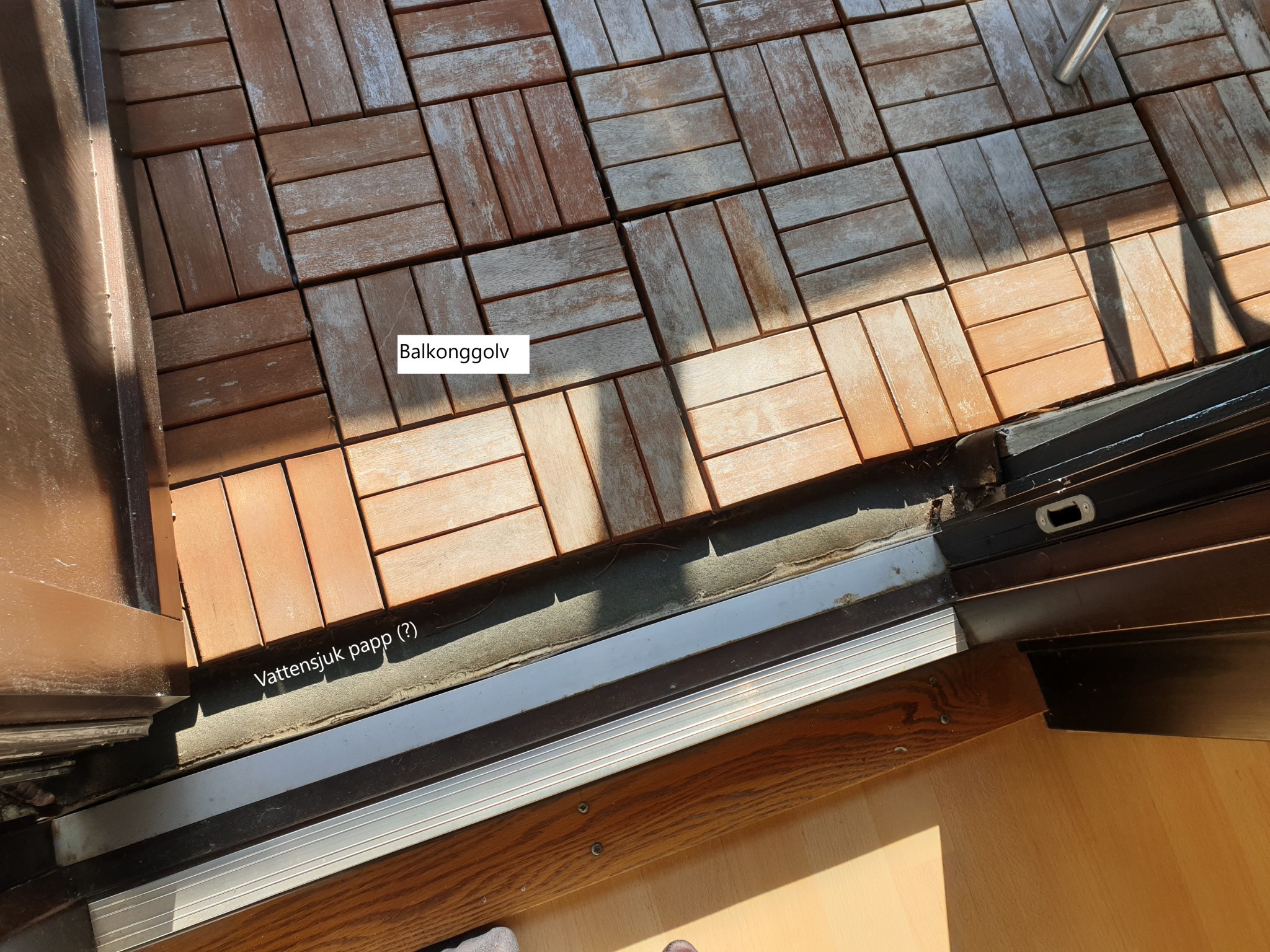
What now seems to be problematic is the roof. I visited another neighbor and looked at how their sunroom was built, see pictures.
Unfortunately, it wasn't built correctly; the balcony felt like walking on a waterbed. I don't know what they did other than lay felt under deck tiles (see picture). But from underneath, it was a very nice roofing solution that made the room bright, so if it were possible to do correctly, it would be great.
So, current situation:
- The post load is about 4kN (400kg) and can be replaced in the way I hoped from the beginning (except that the roof beams in my sketch go the wrong way....)
- After unscrewing the sheet metal to check, it doesn't seem impossible to unscrew the deck boards on the balcony to access and do a proper roof. I think I'll create a new thread about this focusing on sealing against the wall, drainage, and insulation. Weather permitting, I'll spend the weekend unscrewing the entire metal and see what dimensions the current construction has.
- I need to figure out how many ground supports I need to support the entire structure and draw a new sketch with measurements for the beams. But I can't make the drawing until I know how the roof will be constructed. However, I am grateful for tips if there are any other critical points I should consider or read up on.
There are reasons why I suspect your neighbors have cheated: It is a tricky construction project, with no small amount of Catch-22 built into it. Somehow, the balcony's waterproofing must be integrated with the sunroom's. This likely requires you to dismantle parts of the balcony. Many also do not realize that you have to account for quite large service loads on balconies. I think it's good that you're taking it easy and being methodical.
There are reasons why I suspect your neighbors have cheated: It's a tricky construction project, with quite a bit of Catch-22 built into it. Somehow, the balcony's waterproofing layer must be integrated with the conservatory's. This probably requires dismantling parts of the balcony. Many people also don't realize that you need to account for quite large live loads on balconies. I think it's good that you're taking it slow and methodical.
Finally, there's light at the end of the tunnel!
I have now gotten in touch with the carpenter who previously lived in a similar house and built a conservatory. This conservatory was built in 1985, warm, dry, and shows no signs of wear despite its age.
The major problems with the project are
a) the balcony's load (replacing the post) and
b) the balcony's, and subsequently the conservatory's, waterproofing.
We have already determined that the balcony's load should be able to be supported by a transverse beam resting on the front horizontal beam above the sliding doors. This solves problem A.
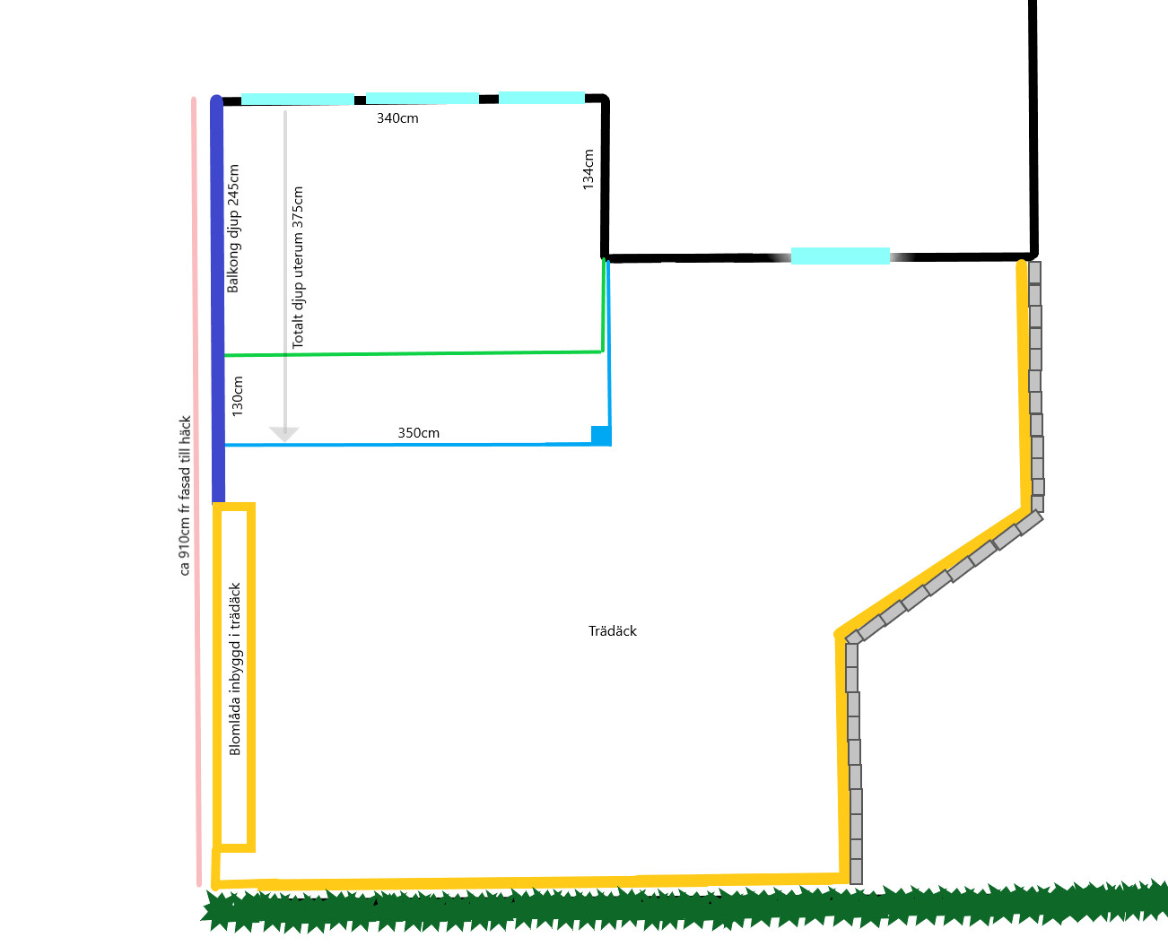
To simplify the construction, I've also decided to skip the side extension, as it's simply causing too much headache. So the conservatory will extend straight out in front of the balcony, but not to the side, see new sketch (the measurement that is 340cm might actually be 360cm, this needs to be remeasured).
Additionally, the solution will be that the balcony's waterproofing is maintained and completely separate from the conservatory's (more on this below).
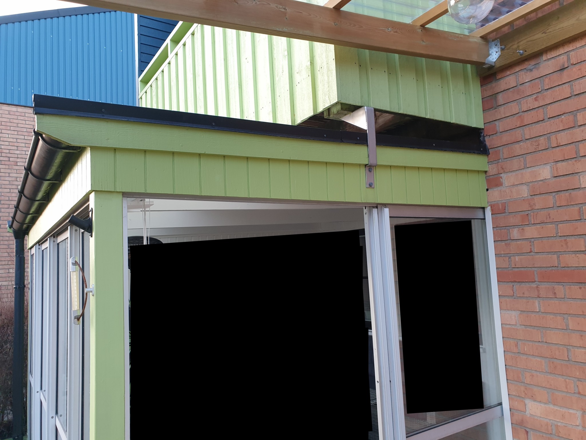
The picture shows the conservatory built in 1985. The angle bracket supporting the balcony is likely custom ordered.
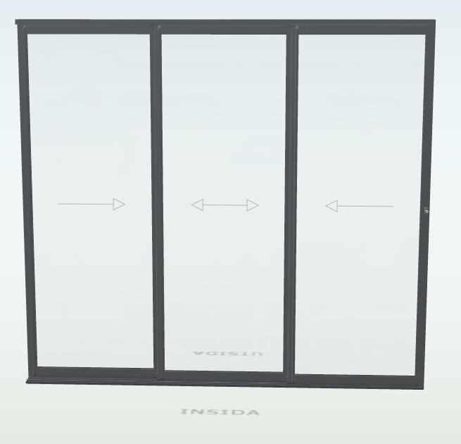
The only difference I hope to make is to have the sliding doors go outside the brickwork; in the picture, they retract behind the brick wall. With 3 sections of about 73cm, it results in a door opening of about 140cm in maximum open position, which is quite sufficient.
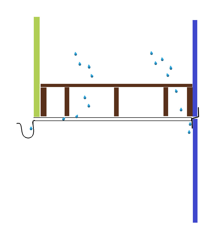
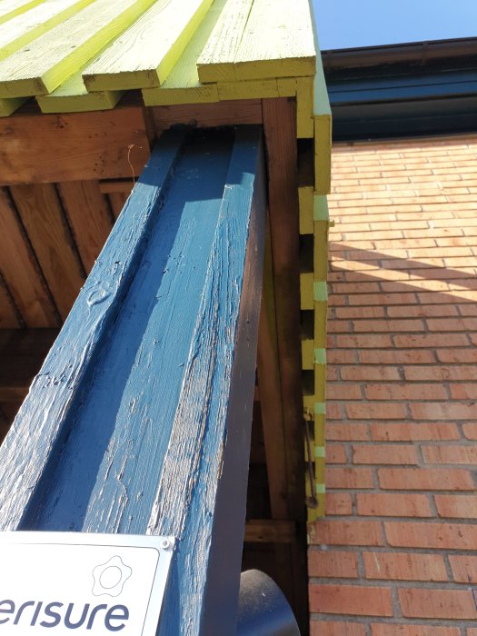
Waterproofing/drainage: The current drainage from the balcony looks like this:
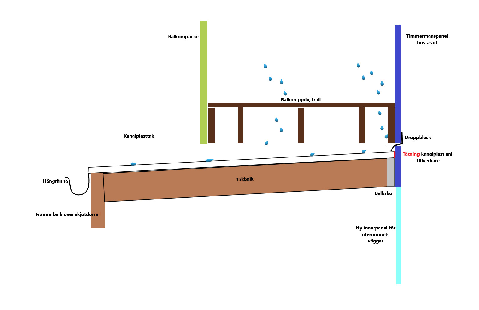
The new construction simply involves removing the corrugated sheet under the balcony, and bending out the existing drip edge (the black sheet metal) or replacing it if necessary. The wall lacking a drip edge and the brick parts in each side wall will also be equipped with a drip edge (sealing against brick parts remains to be solved). Under this, a polycarbonate roof is installed all the way in; it's not the most beautiful but it's good enough. I thought of increasing the thickness, to 35mm or 50mm, to make the transition between dark and light in the ceiling softer/more diffuse. Water is directed on the top of the polycarbonate roof to the front gutter.
This is the solution from the well-built conservatory from 1985, so I hope this will now solve my issues. Feedback is welcome!
The next steps are to:
- remeasure
- calculate the dimensions of all the parts in the frame construction
- calculate what foundation is suitable, both for the conservatory and for the remaining decking. I suspect the conservatory requires a different foundation than the decking, which can manage with slabs if needed. What might the conservatory require for a foundation? Ground screws? Cast slab?
The foundation and frame construction are what I definitely don't feel capable of doing myself... Drip edge, laying polycarbonate, laying decking, and installing sliding doors I should be able to manage.
It seems like the carpenter knew what he was doing. Skipping the protruding part of the conservatory laterally seems wise to me. The foundation completely depends on the type of ground you have in front of the balcony. Posts should always be anchored in footings so they cannot move sideways.
It seems like the carpenter knew what he was doing. Skipping the protruding part of the conservatory laterally is wise, in my opinion. The foundation completely depends on the type of soil you have in front of the balcony. Posts should always be anchored in piers so that they don't move laterally.
Another neighbor's experience says topsoil about 20-30cm then packed macadam. There are about 100 houses built in '79 so the soil should be worked. I am leaning towards hiring a company for ground screws (like slutagräv.se) to avoid hauling gravel and digging loads of soil. Sure, it would be fun to rent a mini excavator, but I mostly just want to finish the deck + conservatory... and I'll fight enough with the rest... saving digging for paving on the other side of the house . Pouring a slab with L/U-elements also seems fun but is probably overkill.
Then the little Yodan went out and bought a decent screwdriver and started dismantling the sheet metal under the balcony.
I hope enough information is evident from the pictures.
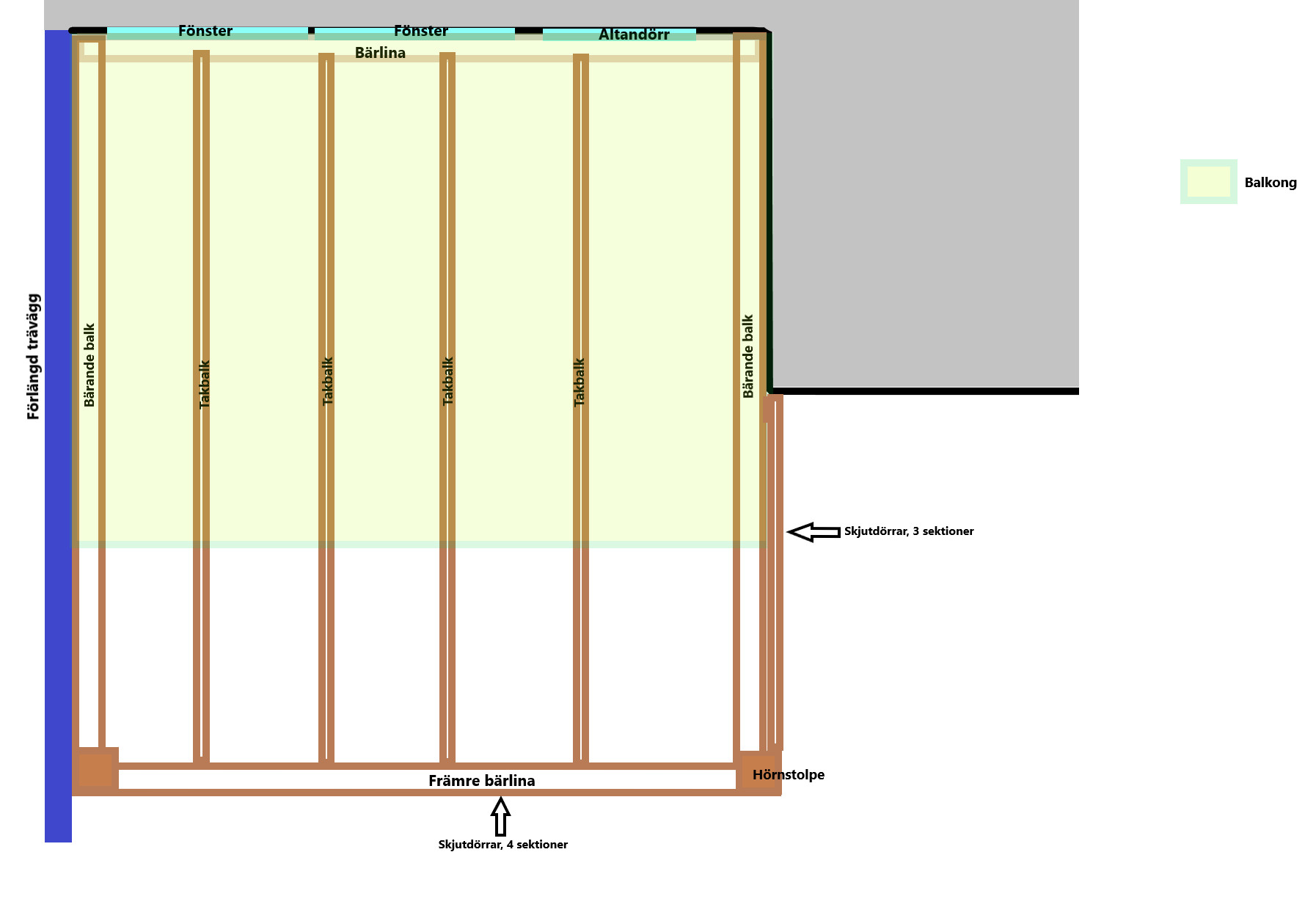
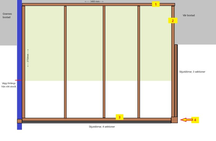
The current post is offset 7cm in from the right edge.
What I want is for the new corner post to be shifted maximally to the right.
The idea is that the inner part of the post supports the right beam (no. 2) and the outer part of the post supports an additional beam over the sliding doors. I want the side doors to start at the brick, just as the outer green panel of the balcony does in the picture above.
New sketch of frame:
Beam no. 2 is then the one where the bracket supporting the balcony will be attached, together with post no. 4.
I can probably figure out the intermediate rafters myself, but if, for example, @justusandersson could help me with which dimensions I need to have on the numbered beams, I would be endlessly grateful. It is desirable that the post and front beam are as narrow as possible to enhance the view, while simultaneously ensuring I have a stable construction. Unfortunately, I have dyscalculia and therefore find it difficult to read dimension tables.
The idea is for the conservatory to have its own foundation with insulation, and the wooden deck around it will be built separately to prevent moisture from entering via the beams in the floor layer.
I have simplified it somewhat for myself, which implies a slight over-dimensioning that you will have to tolerate. Glulam 66x225 should suffice for the three beams. Post in glulam 90x90. Construction timber can also be used, but glulam is more solid. If you want the beams to be narrower, 42x270 will work fine.
I have simplified it somewhat for myself which means a slight overdimensioning, which you have to put up with. Glulam 66x225 should be enough for the three beams. Post in glulam 90x90. Construction wood also works but glulam will be best. If you want the beams narrower, 42x270 will do.
Jjustusandersson said:
Forgot to praise the nice and educational pictures with explanatory text. Which program did you use for that?
Thank you so much for this Justus! I can't find any glulam beams that are 66x225 (only 56x225 or 66x315) but I will go to the building supply store this week to see if it's possible to get them. It would be fantastic if it can be arranged so that the height remains at 225, the width doesn't matter but the height of the beams is important so that the glass doors have at least 2000 in height. Is it possible the other way as well, i.e., if 90x180 would work too?
Drawing program: After trying Sketchup (and wanting to throw the computer out the window...) I returned to good old Paint, though Paint 3D (standard Windows program). So it's freehand and 2D shapes. It has its limitations but works. Lacking the ability to handle numbers (I can calculate/estimate, it's just the numbers that are tricky) I have acquired a decent sense of proportions and a good eye for measurements. Thanks for the praise!
Unfortunately, I am a dedicated Macintosh user, so I don't have Paint for Windows. I have been looking for a program that can handle both raster and vector graphics simultaneously without costing a fortune. Right now, I am testing Affinity Designer.
Click here to reply
Vi vill skicka notiser för ämnen du bevakar och händelser som berör dig.