3,369 views ·
13 replies
3k views
13 replies
A classic: Is the wall load-bearing?
Hello.
I wonder if anyone knowledgeable dares to comment on load-bearing walls given the following floor plans?
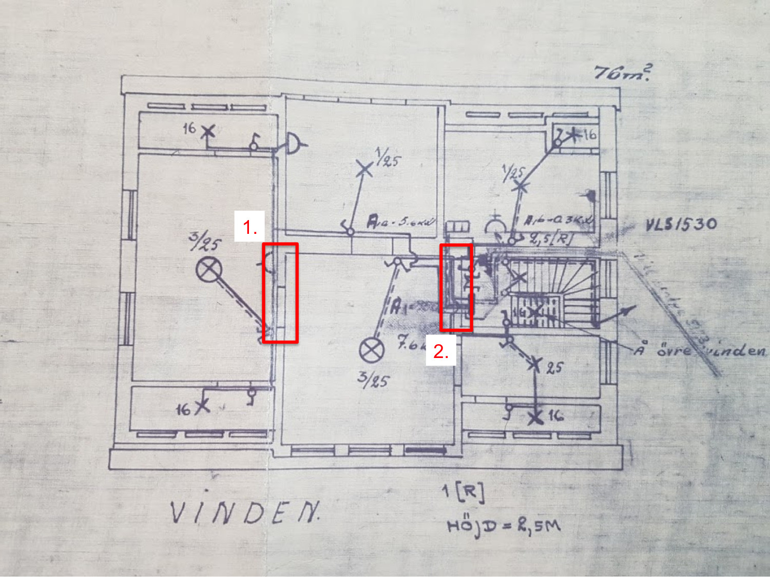
1 1/2 story villa built in 1926. Exterior walls made of brick+plaster. The ground floor has a masonry wall that runs across the middle of the house. The same wall runs almost along the entire upper floor (except in the room to the far left).
So to the questions:
1. Is the wall marked with 1 load-bearing? I'm thinking of dividing the room and want to add an extra door...
2. Is the wall marked with 2 load-bearing? There I plan to take down about 150 cm to open up towards the staircase.
Grateful for answers and thoughts
I wonder if anyone knowledgeable dares to comment on load-bearing walls given the following floor plans?
1 1/2 story villa built in 1926. Exterior walls made of brick+plaster. The ground floor has a masonry wall that runs across the middle of the house. The same wall runs almost along the entire upper floor (except in the room to the far left).
So to the questions:
1. Is the wall marked with 1 load-bearing? I'm thinking of dividing the room and want to add an extra door...
2. Is the wall marked with 2 load-bearing? There I plan to take down about 150 cm to open up towards the staircase.
Grateful for answers and thoughts

As always: You'll notice... 
Nah, but seriously. An old good rule of thumb is that load-bearing walls usually run along the length of the house, perpendicular to the roof trusses. The long masonry wall in the middle is probably the famous heart wall.
I find it hard to believe that number one in the picture is load-bearing. Not least because it looks like, according to the blueprint, it's not directly above the corresponding wall on the lower floor. Besides, it's in the transverse direction of the house. That doesn't necessarily mean it isn't load-bearing, but it suggests that it probably isn't.
Number two - isn't that the chimney? It's a bit hard to see on my phone.
Member
· Södermanlands län0
· 983 posts
If the ridge beam runs horizontally in relation to the drawing and the lower rafters of the trusses therefore run vertically in relation to the drawing, then no load-bearing walls are marked. The drawing's horizontal wall, which is drawn through both floors and thus runs along the house, is, however, load-bearing based on my assumption. If the roof structure looks different than a ridge roof from left to right, then the situation may change.
The ridge beam runs horizontally and the wall on the ground floor is completely removed without a lintel. You can see a faint cross over it.
It is not visible in the picture, but it is not the chimney. That is built into the so-called heart wall.
Today, wall 2 is opened about 70 cm and the door you see a little further down the wall is sealed off. My plan is to open up so that the wall aligns with the adjoining room. It will be about 90 cm extra to remove.
This is what the wall looks like today...
A follow-up question. How is the ceiling supported in the left room on the upper floor, do you think? Are they the trusses? Do they have beams over 7 meters long?

Last edited:
Aha, now I get it. No, it's probably not load-bearing, I find that very hard to believe.S Sebastian Courel said:

In a 1 1/2 story house, there are usually no load-bearing walls on the upper floor. The ceilings rest partly on the collar beam of the roof trusses (which runs horizontally) and partly on the rafters (the sloping parts) of the roof trusses. If there are other conditions that need to be considered (e.g., various supports), they are usually indicated in the sectional drawing. The upper floor's layout gives a somewhat unsystematic impression, so you should be observant. In older times, construction was a bit haphazard. There are also two dormers whose construction is not shown in the floor plan. By looking at the attic, it is usually possible to see the roof structure most clearly.
Thank you for all the responses. It is really appreciated!
Unfortunately, I don't have a sectional drawing. However, I have checked the attic and formed an idea of how the trusses are positioned.
Attached is a picture of the gable with beams drawn in. Where the roof breaks, it's about 7 meters in width. At the eaves, it's about 9 meters. Do you think there are whole beams running the entire way?

It is a very stylish house. Typical 1920s classicism, or Swedish Grace as it was also called. An extra reason to be a bit careful in social interactions. The broken roof and the large height of the attic make the rafters a bit special. It is unlikely that the attic floor beams could span 7 m without support, but not entirely impossible. It depends on the dimensions of the beams. At that time, there was access to a much larger selection. The collar beam is in this case the uppermost horizontal beam. When I look at the floor plan, I see that the support posts for the rafters must be in different positions at both ends of the house. The intermediate floor is guaranteed to rest on a central wall.
Most things indicate that the desired openings can be made, not least the fact that the transverse partition walls on the upper floor do not stand directly over the corresponding walls on the ground floor. However, I would feel more secure if you could draw the attic floor beams on the floor plan and also specify their dimensions.
Most things indicate that the desired openings can be made, not least the fact that the transverse partition walls on the upper floor do not stand directly over the corresponding walls on the ground floor. However, I would feel more secure if you could draw the attic floor beams on the floor plan and also specify their dimensions.
The top blue short beam is actually just two boards attached to each side of the truss.
Just to clarify what needs to be measured... the dimensions of the beams that lie in the floor in the attic, i.e., the beam that lies between the small attic window and the upstairs? And draw where they are located in relation to the upstairs.
These beams are certainly supported by the so-called "hjärtväggen." However, they have no support in the left room...
That "hanbjälken" at the top consists of two boards is completely OK. It is only supposed to take up tensile forces. It is the dimensions of the beams between the attic window and the upper floor that I am interested in. You can see on the floor plan that they have a shorter span in the left room (the supporting legs are further in the room).
Hello. Sorry for the delay... some regular work got in the way...
The dimensions of the beams are about 12x9 cm. They are not precisely sawn exactly.. Then I have carefully measured how the support legs are positioned and the span is the same on the left and right parts. What you see on the original drawing are storage spaces that existed in the room from the beginning. The floor plan looks a bit different now. I am attaching a current floor plan where I have drawn where the attic floor joists go. As you can see, there are support legs for almost every beam except where the dormers are. I have marked the support legs with a green X. I suspect that some of the support legs were removed over time to make better use of the space.
I'm starting to feel comfortable that the walls are not load-bearing but a bit uncertain about how the roof beams in the left room manage entirely without support for 6-7 meters... There aren't really any direct loads to speak of on these. The weight from the roof is transferred to the outer wall that the beams rest on.

Last edited:
9x12 cm corresponds to approximately 5x15 cm, i.e., 2 inches 6 according to older terminology. Without other loads than their own weight, they can handle a 6 m span. The removed support legs are not good; in principle, they should be restored. In summary, I believe you can create the openings you have in mind.
Click here to reply