
2,933 views ·
12 replies
3k views
12 replies
Tips on how I can "splice" a floor beam
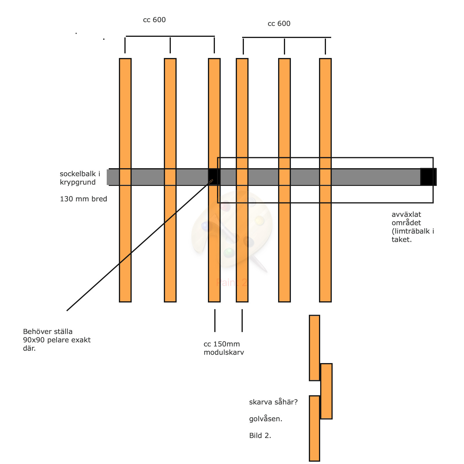
Hi, I'm in the process of removing a wall in the kitchen and encountered an issue with a floor beam that aligns right where I need to place the pillar, to avoid having to move the electrical panel. I'm thinking of something like what I've drawn in image 2.
Or maybe there's a better way to do it? The floor beam notch will be 90 mm, and the base beam in the crawl space is 130 mm wide, so there will be a support of 2 cm on each side remaining. Also, it's right at a module joint.
I can add that I have another base beam in the crawl space located 2600 mm beside it, so the floor beam/floor structure has two "support lines."
Grateful for any responses and tips.
Or maybe there's a better way to do it? The floor beam notch will be 90 mm, and the base beam in the crawl space is 130 mm wide, so there will be a support of 2 cm on each side remaining. Also, it's right at a module joint.
I can add that I have another base beam in the crawl space located 2600 mm beside it, so the floor beam/floor structure has two "support lines."
Grateful for any responses and tips.

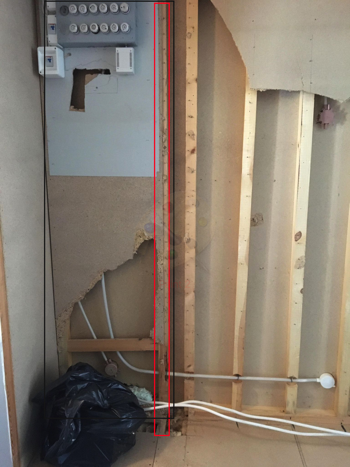
So you have some kind of prefabricated type house? I would like to see an image showing how the floor modules are placed in their entirety. It shouldn't be a problem, but you can't say for sure with your pictures. They are too "cut off."

In general, columns should not rest on beams. If the column load is large, which is likely the case here, the shear forces can become too high for the beams. Widening the beam could be a solution, but it should be verified first. Without a drawing showing the entirety, it is not possible to say more at this time.
I want to see a dimensioned or scale drawing so one can determine how long the beams are. Small sections can explain but cannot be calculated on.

Can't find my messages right now. They have changed the interface. Will search later. Just a small calculation example. If the beam is 3 m long and subjected to a uniformly distributed load of 15 kN/m, the column load will be 22.5 kN per column. Looking at the TräGuiden's table over construction timber, a 45x220 beam can withstand a shear force of max about 12 kN. Two screwed together can then handle double, i.e. 24 kN. In this case, it is the cross-sectional area of the beam that counts.
Framed wall section (black box in the picture with the electrical panel) where the column will stand will remain should help relieve the column as well?
Calculated with 20kN column load.
190 x45 joists unfortunately, but maybe it is possible to block in 195x45 alongside anyway?
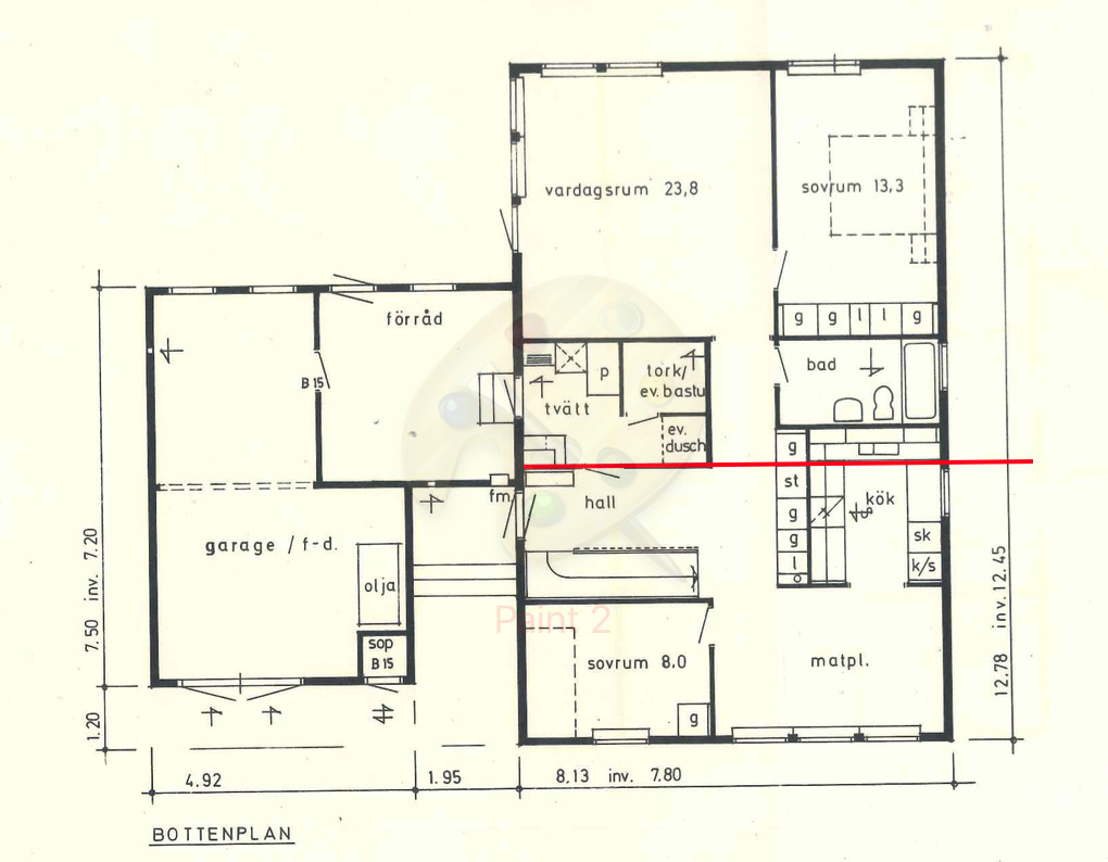
The red line on the floor plan is where the module joint goes. PDF file at the bottom.
Calculated with 20kN column load.
190 x45 joists unfortunately, but maybe it is possible to block in 195x45 alongside anyway?
The red line on the floor plan is where the module joint goes. PDF file at the bottom.
As already mentioned, place a bracket on either side of the base beam that the cut floor joist will then rest on. Alternatively, move the pillar slightly to avoid the floor joist. In any case, the pillar should go down to the base beam and not stand on the floor beam.
Thank you for your help, one last question.
Is this screw sufficient to fasten it together?: https://www.byggmax.se/träskruv-c4-60x180-p249681
Or should I go straight for buying this type: https://www.beijerbygg.se/privat/sv/produkter/fästdon/skruv/träskruv-utvändigt/träskruv-topkon-hex
Is this screw sufficient to fasten it together?: https://www.byggmax.se/träskruv-c4-60x180-p249681
Or should I go straight for buying this type: https://www.beijerbygg.se/privat/sv/produkter/fästdon/skruv/träskruv-utvändigt/träskruv-topkon-hex
Click here to reply