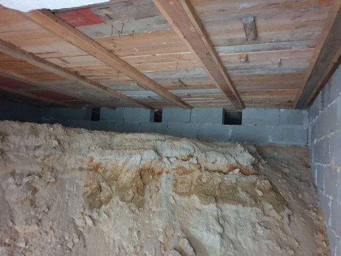
Underneath it, I will be digging a basement (for various reasons)
To succeed with my project, I will need a beam almost in the middle under the house.
Currently, there is an existing sill (of which I - at the moment - don't know the height/width)
It supports the floor joists. - As I understand, the trusses are self-supporting, meaning the weight doesn't rest on the beam but on the outer walls.
Under the sill (which lies on the concrete block in the picture), I was thinking of placing a steel beam to get a free floor area.
I started planning for a glulam beam (but this summer it's not the right time to buy one)
So I need to get a steel beam. (then maybe a steel beam provides a slightly lower building height?)
I'm looking for a suitable type (HEA / HEB / HEM / IPE) that builds the least in height.
Is there a big price difference between the beams?
I have tried to estimate the weight that needs to be supported, but I end up with a good margin at around 2000kg - 2500kg.
The beam should be about 4m + supports.
What else is needed to dimension the beam?
Those I've contacted respond with "too small a project"...
Will the contact end up being more expensive than the beam?
What I believe is the problem is that the designer doesn't have "complete knowledge of the situation" and must provide a "guarantee" on the project.
If it had been a new build, they would have "full control" and know the loads to be entered into a program.
Now it involves a lot of assumptions and "feeling"...
The ones I've contacted reply "too small project"...
Will this contact end up being more expensive than the beam?
What I think the problem is, is that the designer doesn't have "full knowledge of the situation" and must provide a "guarantee" on the project.
If it was a new build, they would have "full control" and know the loads that need to be fed into a program.
Now, there are a lot of assumptions and "intuition" involved...
It seems sensitive to answer questions like these, so I will try to give an answer without stepping outside acceptable boundaries.
The price of a beam is, in my opinion, very low. The problem tends to be the shipping, but if you can have the beam cut at the factory, it might become somewhat more reasonable.
Problem number two is that it can be difficult to calculate the correct load on the beam, both the static (constant) and dynamic (varying).
It's not enough to calculate based on what you think you will use the underlying construction for, because then there's a risk the scenario will become very unfortunate for someone else in the future. Do as Baloo and go above and beyond when calculating maximum load!
Problem number three is to achieve a satisfactory anchorage of the beam where the foundation can withstand the load and not succumb over time.
Be very careful and self-critical if you decide to undertake the work!
With these clauses out of the way, we can move on to dimensioning...
I would have drawn a so-called TM-diagram and done the calculation. (shear force and moment diagram)
If you Google it, you'll find everything you need to know.
If you're more practically inclined and want a less theoretical approach, I would download the free version of Autodesk Fusion 360 and draw the beam and distribute the forces. If you want to take a shortcut, download a step file of a beam and import it.
It actually goes much faster and easier than you think, or alternatively, it's just me who is work-injured.
However, the problem of dimensioning for the correct load remains. Let's hope that the folks on the forum don't go bananas when I write this, but you can indeed make an educated guess.
If you're rushed/comfortable/lazy, you can do a quick calculation as a starting point and then considerably overdimension. For example, multiply your calculated weight of the above structure by PI and/or thereafter apply a safety factor (multiply by between 3-10)!
Remember that the beam will always bend, the question is just how much you're willing to accept.
The last resort that works fairly well is to choose a beam with the same construction height, or one step below, as a wooden stud in C24 lumber. If the stud is strong enough to hold, then the beam certainly is too.
However, it usually ends with if the above construction doesn't have to be entirely rigid and doesn't consist of 1-2dm of concrete, I use a wooden stud or alternatively a glulam beam (depending on the span). If you want it stiffer, reduce the CC between the studs. (I've gone down to CC 300mm and even double-glued wood studs, which I then pulled together with bolts.
The cost of the materials is usually the least of the problem, even though the price of wood has risen significantly.
A primary beam of this type (which in turn is supposed to support existing floor joists) should be dimensioned for a very limited deflection. The beam load will be approximately 12 kN/m, which means you end up with an HEA200 or a HEB180. HEM and IPE are not relevant in this context. You must also ensure that the supports can handle the loads that will be applied.
A primary beam of that kind (which in turn will support existing floor joists) should be dimensioned for a very limited deflection. The beam load will be about 12 kN/m, which means you'll end up with a HEA200 or a HEB180. HEM and IPE are not relevant in this context. You also need to check that the supports can handle the loads that will be relevant.
Out of sheer curiosity, what load did you use, what safety factor, and what do you get for fmax?
Is it simply calculated as a distributed load?
Is there any point in fixing the existing floor joists to the beam, or should it only be tensioned against them?
Maybe I can learn something as I am not used to designing for house constructions...
Dimensioning with regard to the serviceability limit. Imposed load plus dead weight should be 3 kN/m2. I have calculated with a maximum deflection of L/600 on the beam since it is a primary beam intended to replace a foundation wall.
Thank you for your commitment! (perhaps not many will have the patience to read my "reasoning"... But I feel the need to clarify some things.)
Ccoccon said:
It seems sensitive to answer questions like this, so I will try to give an answer without exceeding acceptable boundaries.
The price of a beam is, in my opinion, very low. The problem is usually the transport, but if you can have the beam cut to size from the factory, it might be a bit more reasonable.
Problem number two is that it can be difficult to calculate the correct load on the beam, both the static (constant) and dynamic (varying). It's not enough to calculate based on what you think you will use the overlying structure for because then the risk is that the scenario becomes very troublesome for someone else in the future. Do as Baloo and calculate the maximum load generously!
Problem number three is getting a proper attachment of the beam where the substrate can withstand the load and not succumb over time.
Be very careful and self-critical if you decide to take on the work! With these clauses cleared, we can move on to sizing...
I would have drawn up a so-called TM-diagram and made the calculation. (shear force and moment diagram) If you Google it, you’ll find everything you need to know. If you're more practical and want a less theoretical approach, I would download the free version of Autodesk Fusion 360 and draw up the beam and place the forces. If you want to cut corners, you can download a step-file of a beam and import it. It's actually much faster and easier than you think – or maybe I'm just work-damaged.
However, the problem remains to dimension for the correct load. Let’s hope that the forum people don't go bananas when I write this, but you can indeed estimate. If you're stressed/convenient/lazy, you can do a quick calculation and then grossly over-dimension. For example, multiply your calculated weight of the above structure with PI and/or then add a safety factor (multiply with between 3-10)! Remember that the beam will always bend; the question is only how much one is willing to accept.
A last resort that works fairly well is to choose a beam with the same construction height, or one step below, as a timber joist in C24 wood. If the joist is strong enough to hold, then the beam definitely is too.
However, it usually ends with if the above construction doesn't need to be completely rigid and does not consist of 1-2dm of concrete, I use a timber joist or glulam beam (depending on the span). If you want it stiffer, reduce the CC between the joists. (I've gone down to CC 300mm and also double-glued timber joists which I then bolted together. The cost of the material is usually the least of the problem even though the price of wood has increased significantly.
Good luck!
1) The price might "be last" in the prioritization. Low beam height and weight are the most important (with a functional beam).
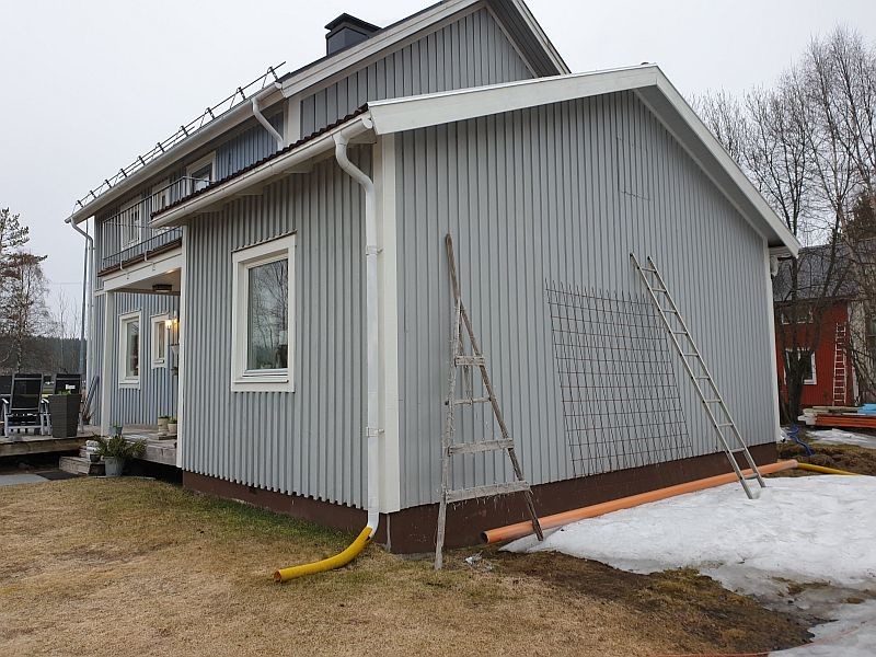
Heavy wooden floor above (with two rooms - one with tiles above)
Living space - occupancy load
L1 = 4000 mm
H = 2100
B = 8000
B1 = 4000
Roof slope = 18 degrees
The only value I think is relevant for this beam is L1 (and possibly B1) I believe the roof trusses are self-supporting and weigh down the outer walls. The result was a load of just over 4000kg (feels like it is in the class of the whole extension’s weight) The closest I came was a glulam beam of 315 x 140 x 4000mm (did not consider supports). Wish for the beam to build down as little as possible to not lose too much ceiling height. _____________________________________________________________________________
The only (that I can understand) is that the floor joists rest on a sill "in the middle". Above the floor, there is a room with tiles and a few wardrobes and a thin interior wall between the wardrobes and a bedroom...
The load that the beam should support cannot be 4 tons. (Then how much does the entire extension on 4x8m weigh?) Everything that rests on the stone foundation/socle can be deducted. That is, the outer roof/roof and outer walls. Remaining are floor joists, floor, and some interior walls.
An attempt at rough estimation (with many assumptions) Calculation of the weight for floor joists - Assume 7 floor joists of 2x4m (divided in the middle = 8m) Assume the dimension 2"x6" i.e., 50x150mm (0.15*0.05*8*7=0.42m3) Assume the wood's weight is 450kg/m3 It would mean the floor joists weigh 189kg (half of which rests on the stone foundation) Load on beam => 100kg (estimation) Assume the floor weighs the same => 100kg on the beam (estimation) Assume the wardrobes in the middle of the building weigh the same = 100kg Then we come to the tiled room (with estimated measures) 3m deep 2.3m high and 3.5m wide, with the tiles weighing 21kg/m2. Short wall is 3m deep * 2.3m high * 21kg * 2 walls ~ 290kg Long wall is 3.5m long * 2.3m high * 21kg * 2 walls ~ 340kg Total about 650kg with half the weight resting on the outer walls = 325kg (haven't deducted openings/doors and windows) Maybe need to add grout - estimate 50kg? Ok - there is a wash stand and a toilet and a bed (with most weight against the outer wall) But estimate 100kg on the beam
Oops I forgot we had a party so 6 guests at 100kg each visited and wanted to stand right in the middle of the extension (the wardrobe). => 600kg Assume I want to indulge in a Jacuzzi weighing 800kg (but most of the weight will be against the outer wall in this case - where the drain is, etc.). But let's say 500kg on the beam.
(The inner ceiling probably hangs on the rafters?)
Now the following estimated load on the beam exists .:
Floor joists 100kg
Floor 100kg
Wardrobes and interior walls 100kg
Tiles 350kg
Grout 50kg
Toilet wash stand 100kg
Guests 600kg
Jacuzzi 400kg
Total static load of beam .: 1800kg I don't know where the remaining 2200kg can be found. (according to the wood guide)
My calculation stops at 1800kg (if I haven't summed wrong) I feel that already in this estimation there is "margin".
The other thing affecting strength is the existing "sill" above the hollow bricks. I have estimated it to be as wide as the sill after the outer wall 130mm (and should be roughly as high as the floor joists maybe 150mm high). It itself will take on a load. Which beam would work with this load? Anything else more robust would increase the "margin". Suppose that the load on the beam increases by 1000kg – which beam would you then end up with?
How much will the existing sill "support"? (all I can say is that it will help – and further increase the "margin", but attachment of it in each wall is poor/non-existent.) Because weight for me is a limitation – A heavier beam becomes more difficult to handle "by hand". An over-dimensioned beam will probably lower ceiling height (which will always be noticeable). Perhaps I must accept a beam of 300kg, to support a load of 2000kg???
____________________________
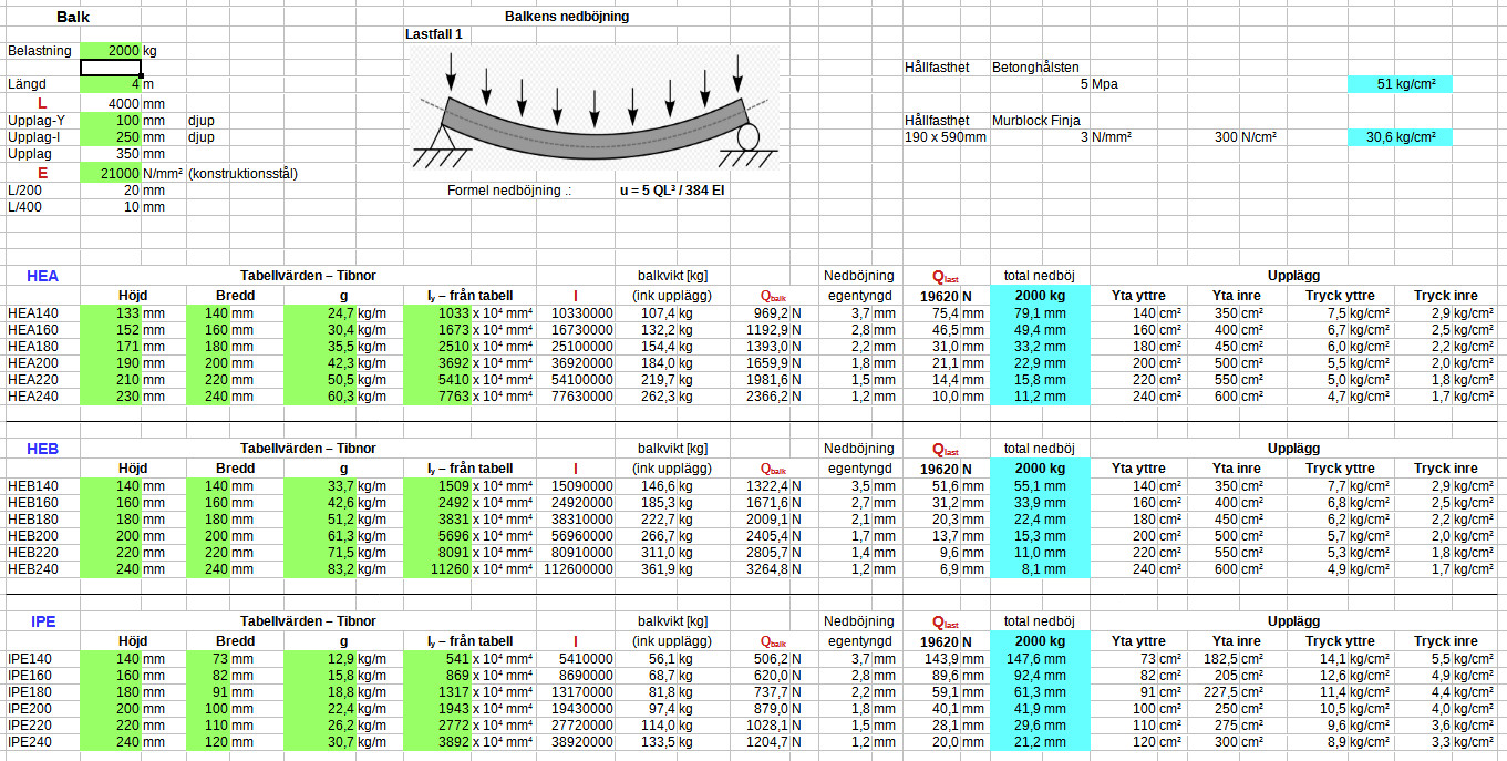
Would gladly do my own calculations .: Deflection at distributed/line load has the following formula .: 5 Q L³ / ( 384 E I )
Q = load [N] (assumed)
L = Length [mm] (existing measurement)
E = Steel's modulus of elasticity [N/mm2] (?)
I = Beam's moment of inertia [mm4] (obtained from table IA)
Deflection at point load has the formula .: P x L³ / ( 192 x E x I )
P = load [N] (assumed)
L = Beam's length between the support points when the point load is in the middle [mm]
E = Steel's modulus of elasticity [N/mm2] (?)
I = Beam's moment of inertia [mm4] (obtained from table IA)
Same here - Steel's modulus of elasticity E (Where is that information found?)
3) Right - attachment is crucial. (but I still feel that the load is moderate - about 1000kg/end) I had planned for the beam to rest on each stone wall (no bolts between beam and wall).
Have looked at TM-diagrams (and formulas) - not completely the wrong path to take - but I didn't find a "suitable" example. The examples I found are based on "bridge constructions" with possibilities for length change. (don't know if it's the same calculations and formulas in this case)
Downloaded Autodesk and eventually managed to "draw something". Haven't figured out what a "step-file" is or where it can be obtained. (a "finished" beam of HEA / HEB / HEM / IPE is preferable - Perhaps its "built-in" values follow?) But it will take a while before the first beam test becomes possible for me.
Jjustusandersson said:
A primary beam of that kind (which in turn is to support existing floor joists) should be dimensioned after a very limited deflection. The beam load is approximately 12 kN/m, landing on an HEA200 or an HEB180. HEM and IPE are not interesting in this context. You must also ensure that the supports can withstand the loads that will be relevant.
With these loads, my intended supports do not hold. – my jacks will fail me. That would mean that the entire beam would be under nearly 48,000kg (then how much does the entire building weigh?) I believe what weighs the most are the outer walls with a tiled roof with a lot of snow...
Can HEA200 / HEB180 really handle this load? What deflection could it result in? Personally, I have a hard time seeing the problem with a deflection of a few cm.
The total load on the beam will be about 48 kN, i.e., 4800 kg. If you accept too much deflection when replacing a wall with a beam, a dip will form in the middle of the floor. I would choose an HEA 200. It is only 10 mm higher than an HEB 180 but 8 kg less weight per meter and has a wider flange which reduces the pressure on the support.
The total load on the beam will be about 48 kN, i.e., 4800 kg. If you accept too much deflection when replacing a wall with a beam, a dip will form in the middle of the floor. I would choose an HEA 200. It is only 10 mm higher than HEB 180, but 8 kg less weight per meter and has a wider flange which reduces the pressure on the support.
Good thought regarding the choice of beam type. Correct about the weight! Thanks! (I got that wrong).
- But I still don't understand where the load comes from.
5 tons from interior walls and floor, and the load-bearing capacity of the existing beam seems to just be a "load."
What does the entire extension weigh then? (Parts of the house in the background I had no problem lifting with a 12-ton jack.)
The largest part of the load comes from what is called "useful load." This is the aggregate value of the floor's usage, i.e., furniture and people. It's typically estimated at 2 kN/sqm in residential buildings. Large portions of the extension's weight, including roof loads, fall on the foundation walls of the long sides and do not affect the beam's sizing.
The largest part of the load comes from what's called "useful load." It is the combined value of the floor's usage, i.e. furniture and people. It is generally estimated at 2 kN/sqm in residences. Large parts of the extension's weight, including roof loads, end up on the foundation walls of the long sides and do not affect the beam's dimensioning.
It's good to have templates, but they are somewhat "rigid" and not always easy to use in renovation situations.
No idea what is included in 200kg/m2.
Based on this, we would get the following load: 200kg/m2 x 4m x 8m = 6400kg.
The perimeter of the extension is 4m + 8m + 4m + 8m = 24m, the length of the beam = 4m, meaning there are a total of 28m sill that the extension currently rests on.
How much deflection of the beam can be "acceptable"?
Even though useful loads may be stereotypes, they are also normative requirements, i.e., not optional. This also applies during renovation. In 200 kg/m², furniture and people are included, but not partitions, installations, and floor coverings, etc.
Thank you for your time and commitment!
Of these 6400kg. Will 4000kg end up on this beam?
How much will the existing sill support?
It is "on the edge" that the existing beam can handle the load. (but it will increase safety.)
What rules exist around "deflection" L/200 L/400 or?
I have created a spreadsheet to get a sense of different types of beams. (I have set the load in the calculation to 2000kg)
However, I have no sense of how much the existing sill will support.
Or will it create two point loads at each end?
Is there a similar formula for wood beams / glulam? (now this is a "regular" wood sill)
Vi vill skicka notiser för ämnen du bevakar och händelser som berör dig.