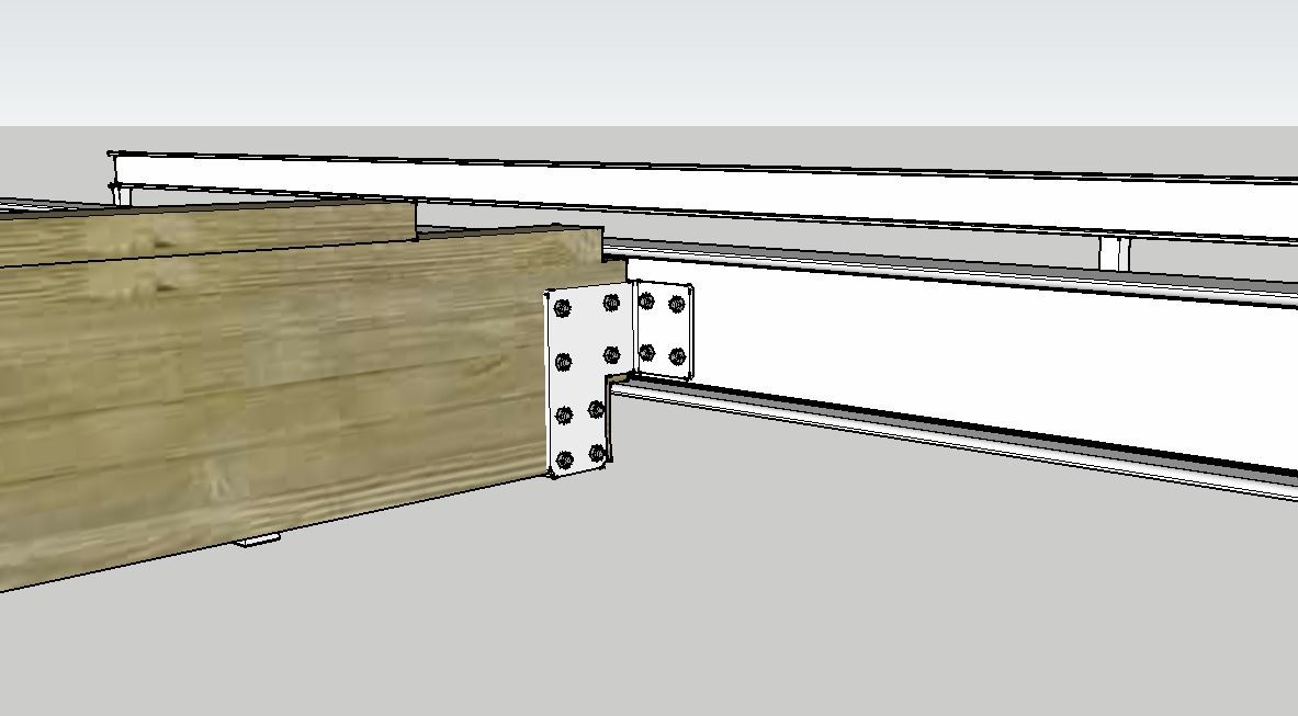
I am going to attach a glulam beam (66x315) to an I-beam (INP 200) as shown in this picture:
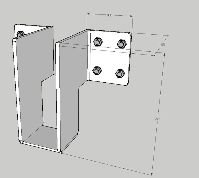
That is, a beam shoe needs to be manufactured, which looks something like this:
The load on this attachment is 13.1 kN. That is, about 1.3 tons will rest on the beam shoe.
Two questions.
1) Dimensioning of this beam shoe. How thick should the material be? Does anyone have knowledge on the subject?
2) Does anyone have tips on a mechanical workshop in the Stockholm area that can help me manufacture two of these beam shoes?
Thanks for the tip, but the bottom edge of the glulam beam needs to be located quite a bit below the I-beam so I don't want to notch so much out of the glulam. There's a high risk of splitting then.
Also, if you just let the glulam rest on the flange on one side of the I-beam, there's a risk that the I-beam will twist.
Bråkis, you seem to have a pretty good sense of how it should be constructed to carry the loads.
Then you should almost have the knowledge to calculate the dimensions too? My guess is 4 mm sheet that you weld or bend, and M10 bolts.
But someone must have dimensioned the steel beam and the glulam beam? He/she should have calculated how the joint should look as well.
We here don't even know what load the glulam beam will be subjected to. (And I can't calculate such things.
but shouldn't the height of the beam bracket against the steel beam be equal to the steel beam's web? Now I think it looks a bit scant there.)
I would probably let a real engineer take a look at that. If I (who am not a mechanical engineer) am thinking correctly, you will get a twisting moment that wants to pull out the upper end of the screw plate. I believe that you will have a lever arm effect that increases the tensile load so that your 13 kN downward can exert a pulling force up to 5 times that at the top of the screw plate. But I could be very wrong.
Bråkis, you seem to have a pretty good sense of how the whole thing should be constructed to bear the loads.
Then you should almost have the knowledge to calculate the dimensions too?
My guess is 4 mm sheet metal that you weld together or bend, and M10 bolts.
But someone must have dimensioned the steel beam and the glulam beam?
He/she should have calculated how the connection should look too.
We here don't even know what load the glulam beam will be subjected to.
(And I cannot calculate such things.
but shouldn't the height of the beam bracket against the steel beam be equal to the web of the steel beam?
Now I think it looks a bit sparse just there.)
The steel beam has been there since the house was built, now it will be extended.
The glulam beam is designed using calculation tables/handbooks and Moelven's design program.
The load will be 13.1 kN from the glulam beam on the beam bracket.
Exactly, I thought 4mm too, because it feels right in the gut, but I don't have any construction calculations on it and haven't found any tips anywhere. I was thinking of having a 4 or 5 mm sheet metal laser cut and then bent. The beam bracket should if possible fill the entire web of the steel beam, you are absolutely right.
I would probably let a real designer take a look at that. If I (who am not a mechanical designer) am thinking correctly, you will get a twisting moment that wants to pull out the upper end of the screw plate. I believe you get a lever effect that increases the tensile load so that your 13 kN downwards can give a tensile force of up to 5 times that at the top of the screw plate. But I could be very wrong.
Good point. Maybe I should play it safe and have my designer (who helped with some other calculations) take a look anyway. Hopefully the summer vacation hasn’t started yet.
Lovely. My constructor thought it didn't need to be so complicated, and that you can simply notch the glulam and then use metal straps arranged in a cross around the I-beam.
Welding special brackets sounds like a bit of an overkill, I think.
I would probably consider two angle brackets on either side of your beam. If you're worried about the beam cracking, which it shouldn't, you can run a threaded rod through it, from top to bottom, to safeguard against cracking.
One does not weld fittings, period.
Make a drawing and have someone water cut and bend.
6mm thickness is a sensible dimension for this solution.
Fill the web of the beam with full-height sheet metal, but do not place the holes too close to the edge of the beam.
Is the steel beam calculated to withstand the load and the torsional moment that the glulam beam will introduce at one point? Since TS says that it is already in place. It might be dimensioned for a completely different load scenario?
Isn't it like going over the river to fetch water?
Gunnebo has many fittings with reasonable dimensions.
[link]
[link]
[link]
I agree, they are very nice. But none of them are suitable for attachment to an I-beam.
Keep in mind that in an I-beam you attach a fitting to the web of the beam. And then the flange is much further out, so the fitting must be designed to extend outside the flange on the I-beam.