I would need some help. I'm planning to build a free-spanning ceiling with OSB and two layers of plasterboard. The hanging load will be around 25-30kg/m2. The span is 4.25m with a 600mm center-to-center distance between the beams. A deflection of 1 cm is not an issue. I need to drill some holes for pipe routing. Will 145x45 or 170x45 suffice?
Need to make some holes for pipe installation. The largest will be for 20mm flexible conduit. Can distribute them with some distance between the holes.
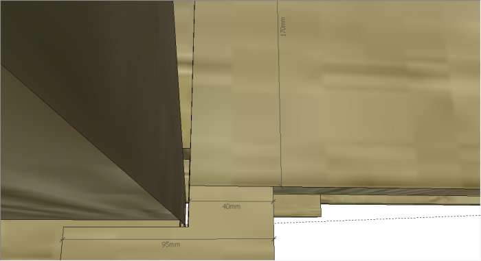
A follow-up question about the load. Will place the ceiling beams on a part of the wall stud, about 40mm. The stud itself is 45x95. Need to do this to avoid contact with the existing wall. Does it work, or does the ceiling beam need to rest on a larger surface?
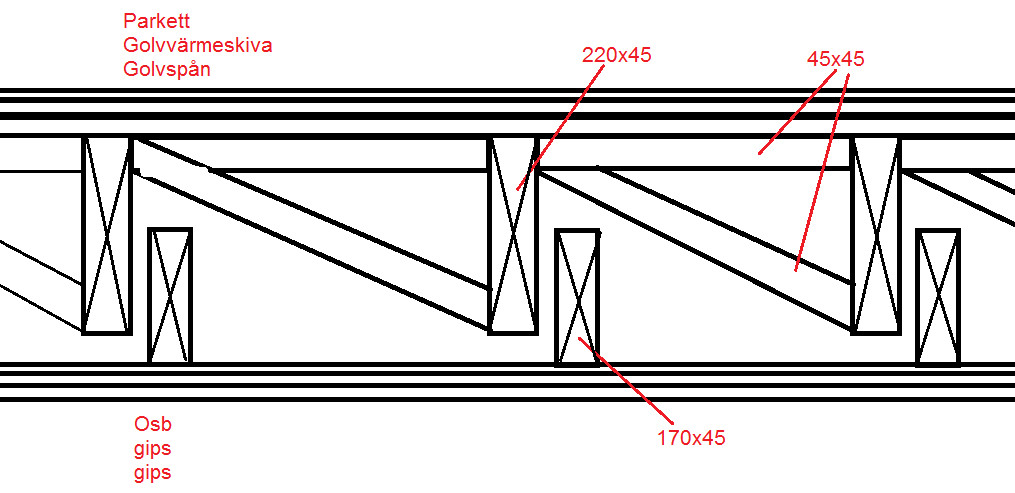
See image
This is a type of room-in-room solution for increased sound insulation.
Single 20 mm holes do not matter much. Avoid the top and bottom edges of the beams and make the holes closer to the supports rather than in the middle of the beam.
A 40 mm support length is on the small side; it is usually recommended to have at least 70 mm. There is certainly a good solution for that, such as some kind of bracket, but then you need to see a detailed drawing to make the right assessment. The beams must be able to be properly fastened and braced against tipping.
If you take 45x170, C14 will suffice. Angle iron and flat iron of a slightly heavier kind will probably work well. I think you can manage this without needing to provide more details.
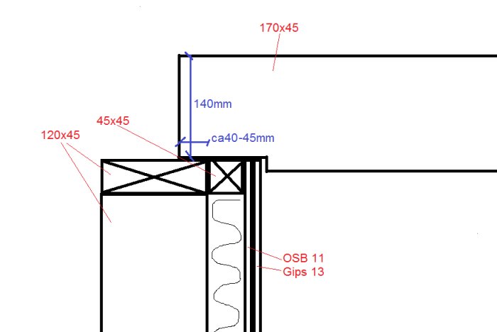
Just want to discuss the mounting on the other side as well. As mentioned, it will be a semi room-in-room, so the other mounting is made against the facade wall. Stabilize so the stud doesn't tip with an angle iron (not on sketch).
So I have to cut out 30 mm from my 170 stud, leaving only 140 mm. Maybe it's just as well to go for C24 class after all, or is that overkill?
Good detailed report, it facilitates the discussion! One should not notch out a beam at the bottom in that way. At the endpoints of beams, it may be OK to notch out on the top side. (However, not where the beam continues over a support in the middle of its length) In this case, the underside of the beam should rest on some form of fittings. Perhaps a flat bar that is bent and folded over the "hammarband". Why do you need to notch out?
I don't quite understand what you mean by "flat bar that is bent and folded over the 'hammarbandet'," maybe you can elaborate on that?
The reason I have to notch it out is because the underside of the beam should lie a few cm below the existing joists so that they are decoupled. This will increase sound insulation significantly.
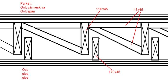
Today between the joists there are braces of 45x45, but there I am thinking of changing it so it becomes a "wedge" according to the sketch above. It has been done that way where the ventilation pipe is installed. Although the wedge is upside down there and provides more stability, I think it should work anyway???
Here's how I think you should do it: Use construction timber 45x145 class C24. Then saw off 5 mm on the future top side of the studs so that they have the dimension 45x140. You can do the sawing with a band saw, construction saw, hand circular saw depending on what you have available. A plunge saw with guide rail gives a very good result. Place the beams without notching on the outer wall. This construction will be more stable than the one you've drawn. The deflection will be marginally larger but still around 1 cm.
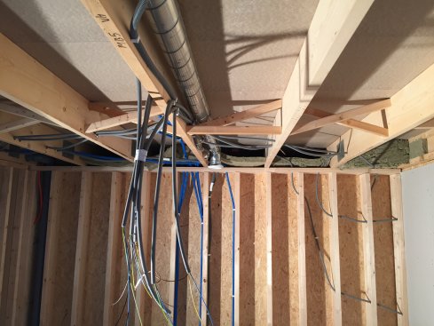
The diagonal braces visible in the picture are a so-called krysskolvning which increases the stability of the joist structure above. You cannot remove or change the direction of them without consequences. You might actually need to add an extra floor joist next to the ventilation duct or alternatively screw-glue reinforcing boards to the affected joists.
Another option to compensate for the removed cross bracing in the compartment with the ventilation duct is to replace it with noggings in the same dimension as the floor joists cut out only for the duct itself,
I think I have space to go with 45x145 straight off without reducing it. So that feels promising, if I rebuild the cross support.
I'm having a bit of difficulty understanding what you mean regarding the assembly. What you see in the photo above is how it looks today from the carpenters. So maybe you mean that the carpenters should have screwed and glued reinforcing boards, added an extra floor joist, or nogging with holes for vent pipes?
If I were to keep the cross support as it looks today, I wouldn't be able to "embed" my 45x145 for the ceiling according to the sketch above without notching the beam so the top side comes below the cross.
Vi vill skicka notiser för ämnen du bevakar och händelser som berör dig.