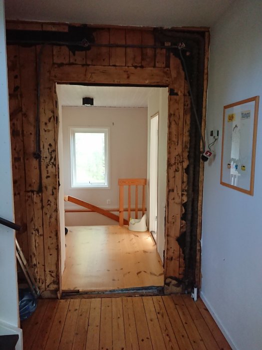
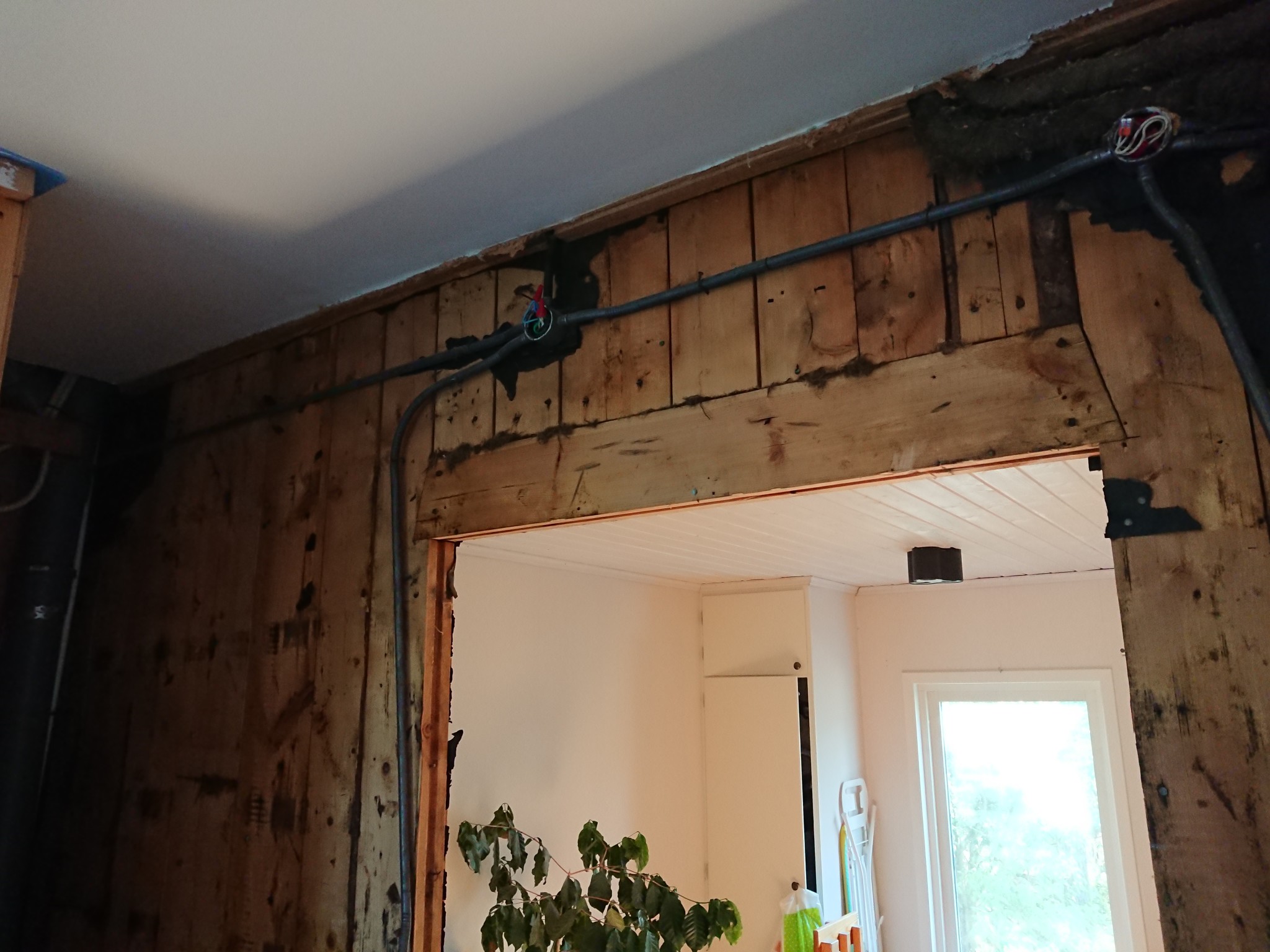
Hello. We have a house built in 1938, extended in 1975. The "joint" between the old house and the new runs along the short side of the house, and the former front door opening is now part of a corridor that runs from the old house to the new one. We are now planning to open this up a bit more to create a more airy and cohesive feel in this corridor and at the same time make space for a WC/shower. The first two images show the current opening (where the former front door was) between the house sections.
The outer wall consists of 65mm thick and about 150mm wide vertical, tongue-and-groove planks that are nailed together, and the current header for the front door is, as seen, only a similar plank laid horizontally instead of vertically. The current opening is 109cm wide. (Incidentally, the house has a number of windows where the opening is 170cm wide, which also have exactly this type of header: a horizontal 150x65mm plank.)
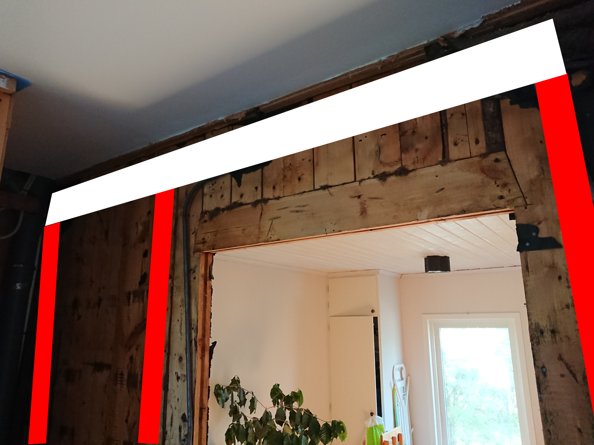
We are now planning to open this up a bit more, both in width and raise the ceiling of the opening somewhat. We intend to do this by placing three posts marked in red in this image: (apologies for the amateurishness)
The right, wider opening would be 137cm and the left about 85cm. We are considering laminated wood columns of 90x90 for the posts. The question now is how to make the support beam (marked in white in the previous image). The maximum height we are aiming for the beam is 15cm. We have considered the following options:
1. Glulam beam 90x180, cut to 15cm height.
2. Steel beam, IPE140
3. Angle steel 120x80x8 or 150x100x10, screwed into the existing planks. So instead of cutting at the top edge of the white marking in the picture, we cut almost at the bottom and let the "lip" of the angle steel go under the existing planks.
Which of these options sounds best and most reasonable? How do they compare in terms of strength? Option 3 might seem odd, but the reason we're considering it is mostly because it would be the easiest to implement and seems like it could be a good option.
The dimensions of the plank are probably 2.5x6 inches. A plank wall functions as a shell construction. All planks are toe-nailed into each other with very thick nails.
Is the opening in the old gable? Why do you want to make an opening that is 137 + 85?
The plank's dimension is probably 2.5x6 inches. A plank wall functions as a shell construction. All planks are toe-nailed into each other with very strong nails.
Is the opening in the old gable? Why do you want to make an opening that is 137 + 85?
The dimension 2.5x6 inches is probably correct, yes. And yes, I know they are toe-nailed into each other, we've noticed that when working with other walls in the house
No, the opening is not in the gable but on the mid-floor, so to speak. The reason for the somewhat strange opening is that we want a shower/WC to the left (in the 85-opening). Sure, we could open all the way (137+85) but since we will still have a wall at 85 measured from the left, we thought it would be an excellent place to reduce the span of any beam by placing a post there.
So what do you think about the alternative load-bearing structures?
I myself have lived for 30 years in a plank house (3 inches) from 1929, so I know from personal experience that you don't remove more planks than necessary. My question about the gable aimed to determine if there are roof loads on the wall in question. I did not receive a satisfactory answer to that question. Generally speaking, it is always good to reduce the span of the opening as much as possible.
I myself have lived 30 years in a plank house (3 inches) from 1929, so I know from personal experience that you don't remove more planks than necessary. My question about the gable aimed to find out if there are roof loads on the wall in question. I did not get a satisfactory answer to that question. Generally speaking, it's always good to reduce the span of the opening as much as possible.
Okay, to provide more information, the opening we're making is on the first floor above the basement in a two-story house. The wall we're making the opening in continues for a whole additional floor above this, and then there's the roof. The roof has no gable in the usual sense but at the top, the roof looks a bit like a pyramid, so to speak, sloping in all directions (with the chimney in the middle).
Reducing the span as much as possible seems obvious to be a good thing, hence the thought to place the "middle post" where we will have the WC/shower room's wall. With this, we will have a span that is smaller than any of the large windows we have on the same floor (where the opening is 170cm).
It's precisely to keep as much as possible of the existing planks that option three feels good. The idea was that you then basically retain 14cm of the planks in height and then screw the angle iron (e.g., 13x6.5x8) to the existing planks, maybe not one screw per plank but at least every other plank is attached to the high side of the angle iron. But I don't know at all how such a solution would stand up against a more traditional support with only one I-beam (since you then have to remove more of the original planks) or a glulam beam (the same as an I-beam and also it won't be as high)...
Before I say anything more, I want to know how the house is built. You probably have a hipped roof where even the gable parts of the roof are chamfered. Take an exterior photo of the house and indicate where the current opening is located.
Before I say anything more, I want to know how the house is built. You probably have a hipped roof where even the gable parts of the roof are sloped. Take an exterior photo of the house and indicate where the current opening is.
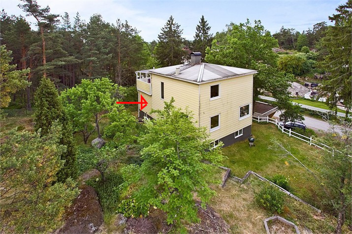
I understand that completely. Unfortunately, there are very few pictures of the house where you can see the roof (it's quite high up). Here is a picture from when the house was bought:
The old part of the house is the tallest (and the one that has a regular roof, so to speak), the newly built part is the one on the far left, the one that ends with a balcony at the top. The wall opening is to be made in the part under the balcony, so if you imagine that the red arrow points through the new wall it is currently pointing at. Another picture from a different angle:
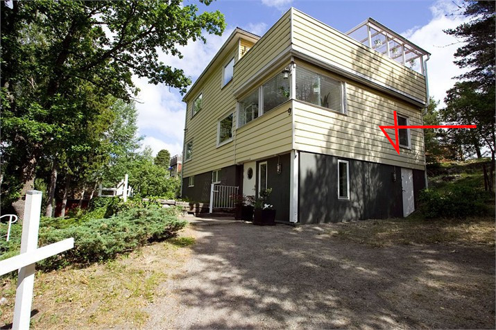
Here the arrow points at the new part's exterior wall, and it's this old exterior wall that runs parallel to it (but inside) that is going to be opened up. I hope this makes things a bit clearer...
I've also dug out the old house's plans. Here is a small overview:
In the top right picture here (which they actually call "Gable" anyway), I've marked in red roughly where the current intended lintel should be placed (it's the old door opening visible in the pictures but from inside the old house, so to speak. As you can see, there was also originally a proper window opening to the left of it, which is now completely bricked up.
I completely understand that. Unfortunately, there are very few pictures of the house where you can see the roof (it's high up). Here is a picture from the purchase of the house:
[image]
The old part of the house is the tallest one (and the one that has a regular roof, so to speak), the newly built part is the one furthest to the left, the one that ends with a balcony at the top. The wall opening will be made in the section under the balcony, so if you imagine the red arrow pointing through the new wall it is now pointing at. A picture from another angle:
[image]
Here the arrow points to the new section's exterior wall, and it is the old exterior wall running parallel to this one (but on the inside) that will be opened up. Hope this makes it a bit clearer...
I have now also dug out the old house's drawings. Here is a little overview:
[image]
In the top right image here (which they actually call "Gavel," at least) I have marked in red approximately where the intended reinforcement will be placed (it's the old door opening visible in the images but from inside the old house, so to speak. As you can see, there was also originally a substantial window opening to the left of it, which is now thoroughly sealed.
Perhaps it's also worth mentioning that the floor joists for the floor above this one run parallel to this exterior wall. The same goes for the floor joists on this floor. The floor joists in the house generally rest on the front and back of the house and not on this sidewall.
Yes, it was a good presentation. From the outside, it resembles the houses that Svenska Trähus in Tranås constructed in the 30s and 40s. But the interior images suggest it was built on-site.
With a slanted nailed plank wall, the horizontal plank over the door opening is not a usual lintel. It should be possible to repeat that technique for the openings you desire, as well as raising the top of the opening. Of course, you can instead use a glulam beam all the way and place a pillar where the wall should be. If you use glulam 90x180 and rip it to 150 mm height, you still have large margins. Just remember that the glulam beam should have the designation h (stands for homogeneous) if you are going to rip it. Common glulam (designated with c) has weaker lamellas in the middle of the beam. Since it is an old gable, there are no floor loads on that wall, which is an advantage.
If you instead buy a 45x145, C35 or C24 (it can be difficult to find C35). Find the straightest and flattest plank you can find at the hardware store. Cut it in half, turn it, and glue them together with plenty of wood glue. Pull tightly with 80mm wood screws to put everything under tension!
If you do it carefully, you'll have a laminated beam that's at least as good as a purchased laminated beam that's been split.
I have done the same operation myself, but I usually plane them first to get completely flat surface areas, but that's advanced if you have a flat joist from the start.
Yes, that was a good presentation. Externally, it resembles the houses that Svenska Trähus in Tranås built in the 30s and 40s. But the interior images suggest it's a site-built structure.
With a skew-nailed plank wall, the horizontal plank above the door opening is not a common beam. It should be possible to replicate that technique for the openings you wish to create, as well as to raise the top of the opening. Of course, you can instead use a glued laminated beam all the way and place a pillar where the wall is supposed to be. If you use laminated wood 90x180 and split it to a height of 150 mm, you still have large margins. Just remember that the laminated beam should have the designation h (stands for homogeneous) if you are going to split it. Common laminated wood (designated with c) has weaker lamellas in the middle of the beam. Since it's an old gable, there are no floor loads on that wall, which is an advantage.
Thank you so much for that; it's reassuring to see that we are not completely off in our thinking. If we're going to cut up to the ceiling and insert some sort of beam, we might as well go with laminated wood, it doesn't hurt to have extra margin (since it should be better than the current 2.5x6 inches).
So my only remaining question is whether the angle steel option is a feasible way forward or not? The idea there was, as mentioned, instead of using wood to brace, to screw a 13 cm high and 8 mm thick steel beam (shaped like an "L") to the side of the existing plank (screwed into every other plank) and let the steel handle the bracing. It might seem strange, but as I see it, there are two advantages: 1. We save more (14 cm in height) of the existing planks. 2. It becomes considerably easier to make the cut 15 cm lower than required if we brace with wood. Shouldn't such a solution be at least as strong as a 15 cm high laminated wood beam? Or is this a completely crazy idea?
If you instead buy a 45x145, C35, or C24 (it can be difficult to find C35). Find the straightest and flattest plank you can at the builder's merchant. Cut it in half and turn it and glue them together with plenty of wood glue. Secure thoroughly with 80mm wood screws to put everything into tension!
If you do this carefully, you'll have a laminated beam that is at least as good as a sawed-down purchased laminated beam.
I have done the same operation myself, but I usually level-plane first to get completely flat surfaces, but that's overkill if you have a planed beam from the start.
Interesting, will it really be as strong as a purchased 90x180 cut down to 90x150?
L profiles of steel have rather poor strength values. You need to go up to quite large dimensions for it to be something. In that case, a square profile is better. However, there are other aspects. It's often easier to stick to wood all the way.
Double laminated and screwed 45x145 C 24 is entirely comparable to a split 90x150 laminated beam.
L profiles made of steel have quite poor strength values. You have to use fairly large dimensions for them to be effective. In that case, it's better with a square profile. However, there are other aspects. It is often easier to stick to wood all the way.
Double glued screwed 45x145 C 24 is completely comparable to a split 90x150 glued laminated beam.
Ok, then it will be wood all the way, thank you very much for the help! One last question, just so I haven't misunderstood the procedure: You split the 145x45:s down the middle, lengthwise. Then you rotate, let's say the upper part, 180 degrees horizontally so that you then glue the two newly sawed surfaces together again, but so that the lower right edge meets the upper's former left edge? And roughly how close should you use the screws? One every 30 cm?
Vi vill skicka notiser för ämnen du bevakar och händelser som berör dig.


")