17,944 views ·
87 replies
18k views
87 replies
Point load on brick wall
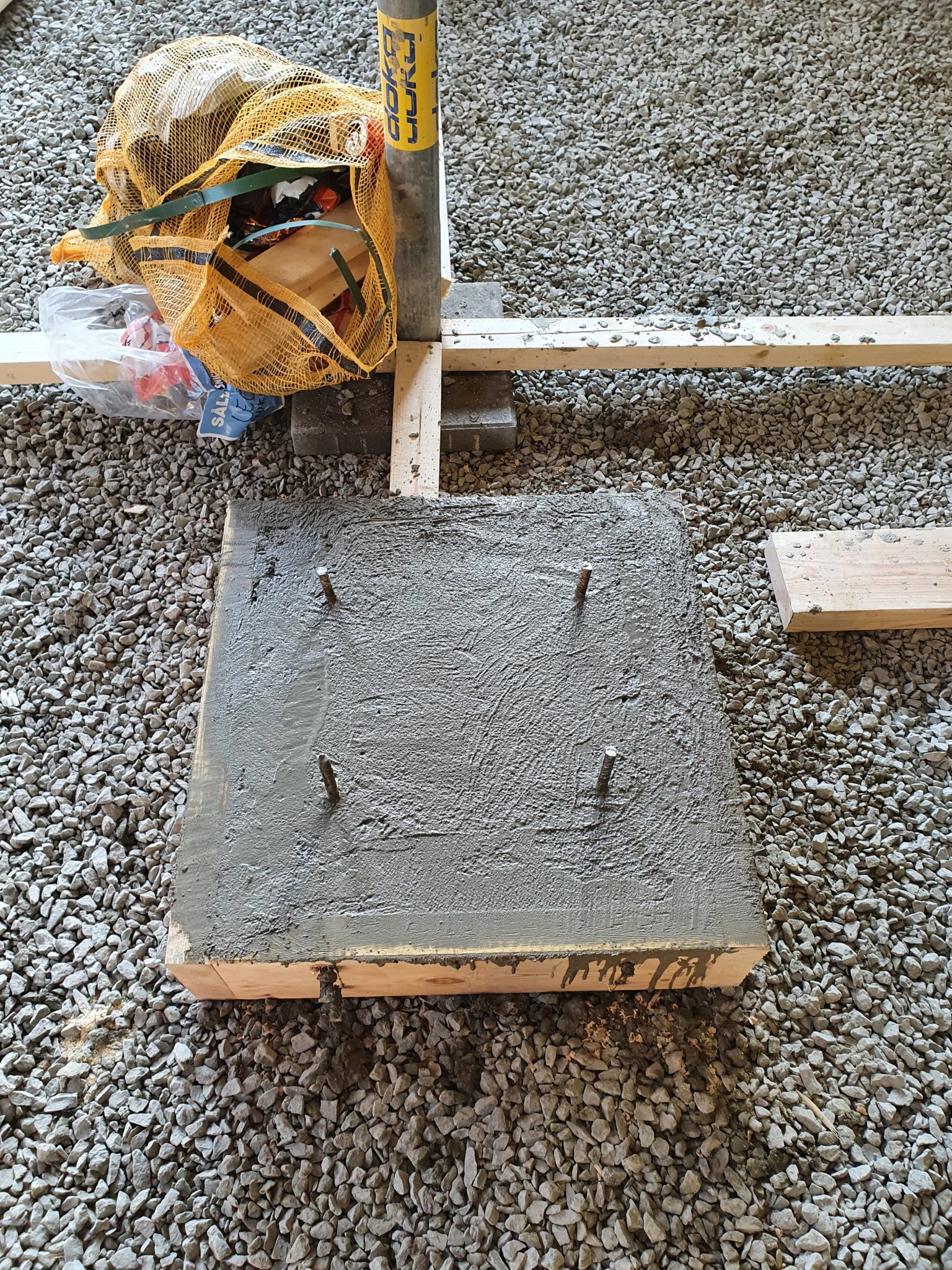
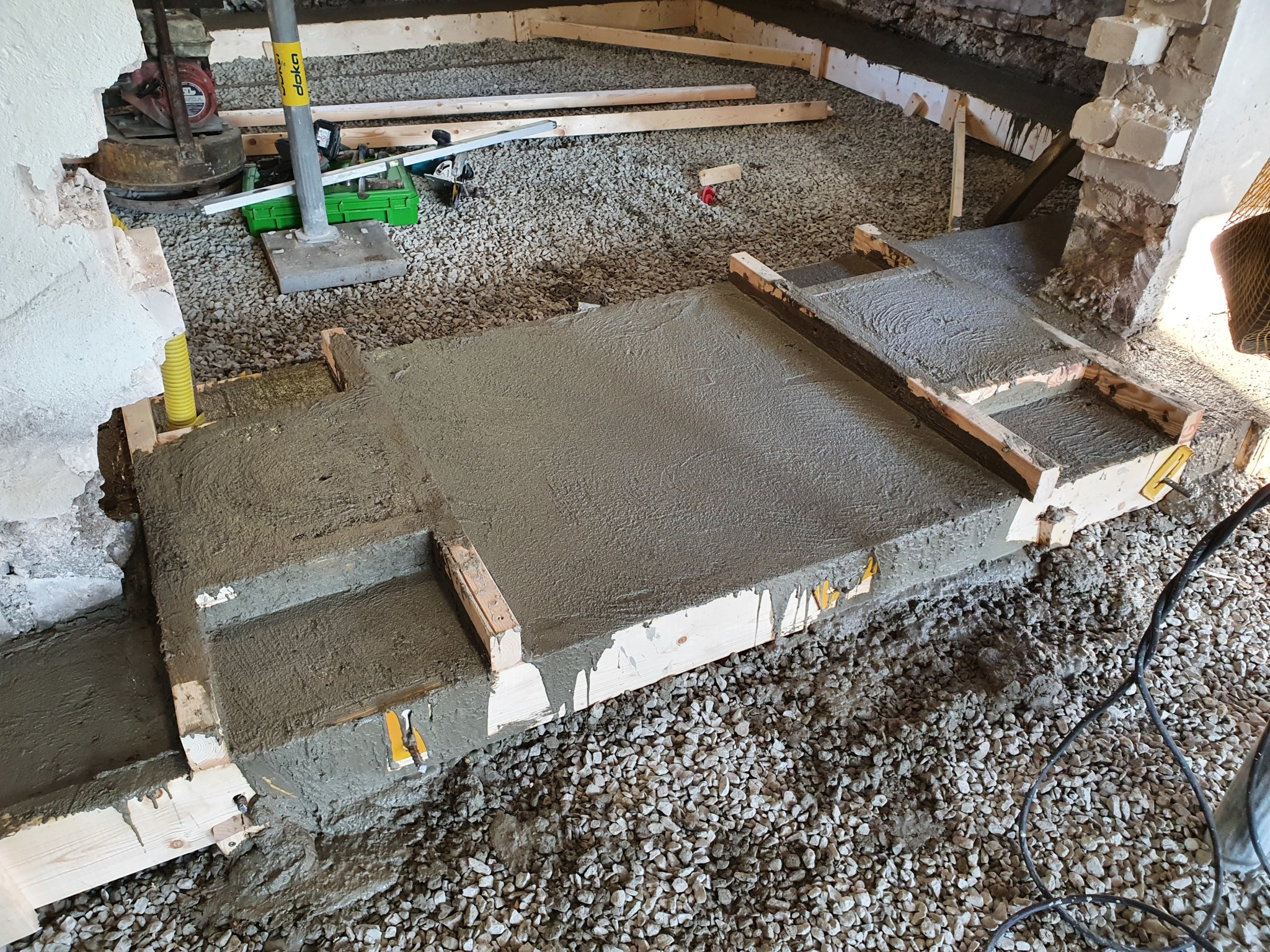
The foundations for the inner columns are already cast. So these are difficult to move now. As you can see, the first foundation is a standalone square block. The second inner column consists of two foundations where I will have two steel columns with a steel beam bridging them.B bossespecial said:How fixed are the column positions? If you increase the length of the middle section, the load on the wall decreases. If it works with the layout, you can find a position where the point load on the wall is zero. However, one should be a little cautious so that the reaction doesn't flip over, causing the beam to want to lift from the wall.

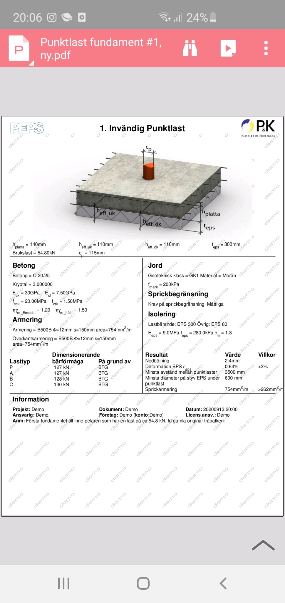
Alright, then we'll have to come up with something else. Is the foundation larger in area under the gravel, it might look a bit small otherwise?
")
Just a small note regarding the calculation in post #1. That calculation refers to a continuous beam, i.e., 10m without a joint. Try to do the calculation again but with a beam supported on 2 supports. Or is a “gerberskarv” intended?
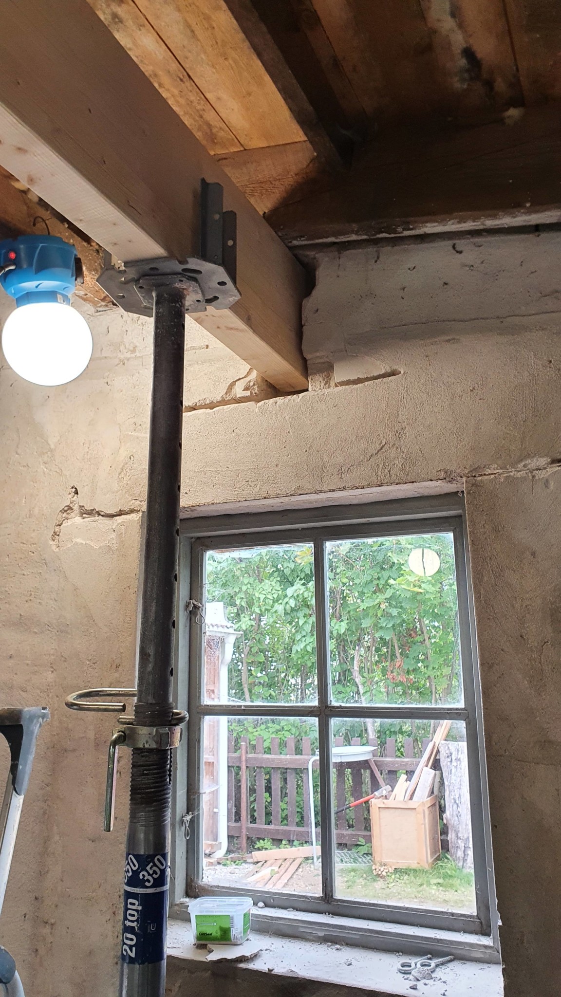
Well observed. I have recalculated and assumed that the two glulam beams act over two independent sections. As if it were two separate houses, that is. The load becomes 25 kN instead of 22 kN. So, an even higher load. I'm starting to realize that such a load is extremely unlikely, but considering how much money I'm spending on this construction, I want to guard against it nonetheless. The idea is that I will build load-bearing interior walls in this section to relieve the brick wall. Of course, I will need to reinforce extra under this line load.B bossespecial said:
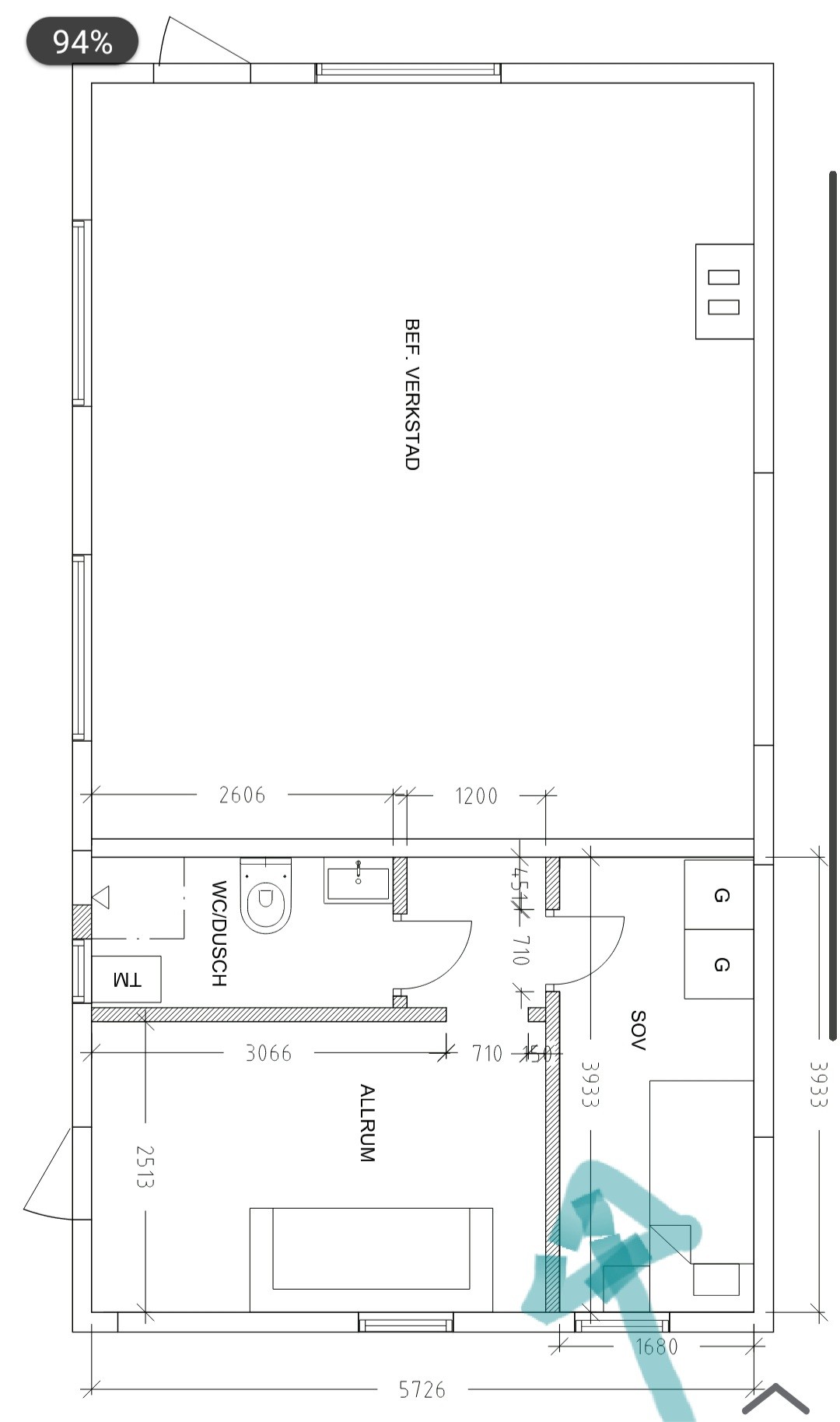
The arrow points to the inner wall we intend to make load-bearing to relieve the brick gable so that not all the load from the glulam beam rests there.
*Note that there will be an opening to the workshop, which is evident in earlier pictures where we have demolished the middle of the wall. The workshop will have the same standard as the rest of the building, although it is not drawn in this floor plan.*
Last edited:
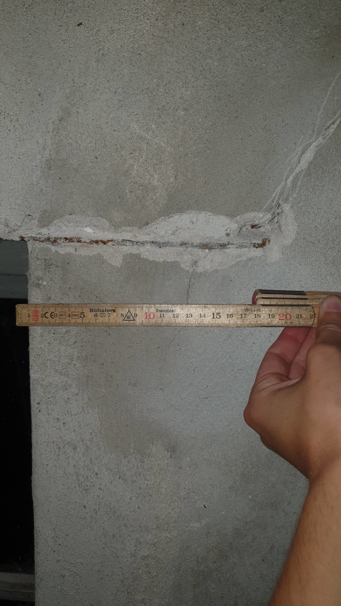
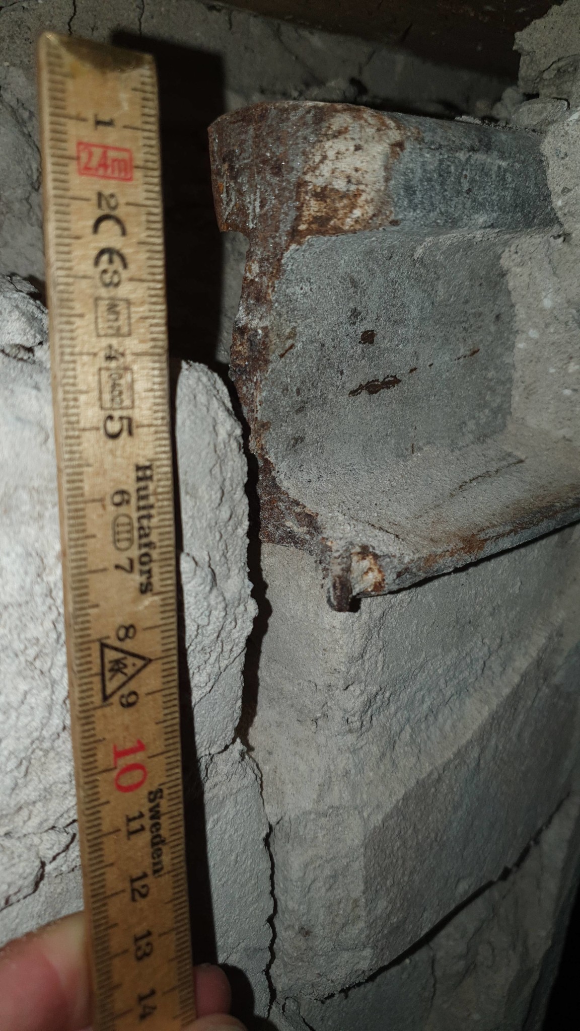

It looks like old railway tracks of the Decauville type (commonly 600 mm gauge). The rail weight is 10 kg/m, which is extremely light for trains. If its span is 80 cm, it can withstand 24 kN as a point load. The question is if the brick can handle it? If my guess regarding the railway tracks is correct, each support surface is 8700 mm^4. If you could reduce the load from the glulam beam closer to 10 kN, I think it would be fine.
I am a bit unsure about how the floor plan relates to the glulam beam and the columns, so I will hold off on commenting about this.
I am a bit unsure about how the floor plan relates to the glulam beam and the columns, so I will hold off on commenting about this.

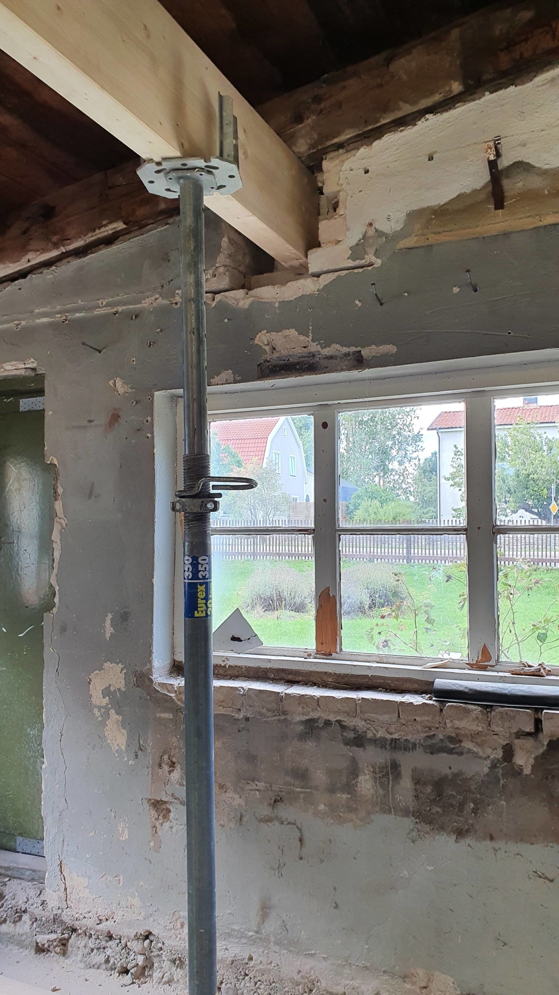
A flat bar under that glulam beam will not distribute much load laterally, it's simply too weak. How wide is the window opening in image 2? It looks like you might have trouble there unless there's a substantial beam over the window opening to handle the vertical load from the glulam beam. If it's the rail according to previous images, it's questionable whether it will hold.
I interpreted the post about recessed flat iron to mean that it was to be used for distributing the load, which it will not do. Yes, it will distribute the load a bit, but not in a way that will help significantly.