L/300 with the point load you calculated can be a good starting point. It’s such a short span that even the smaller HEA beams are surely strong enough. I can see in the picture that you’ve dimensioned the entire beam, the span should be the distance between the columns.
Just make sure to attach the beam to the purlins before you release the prop, or at least before the snow comes
L/300 with the point load you calculated can be a good start. It's such a short span that even the smaller HEA beams are surely strong enough. I see in the picture that you've measured the entire beam, the span should be the distance between the columns.
Just make sure to attach the beam to the rafters before you remove the support, or at least before the snow comes
Haha, I wonder if I've totally messed up.
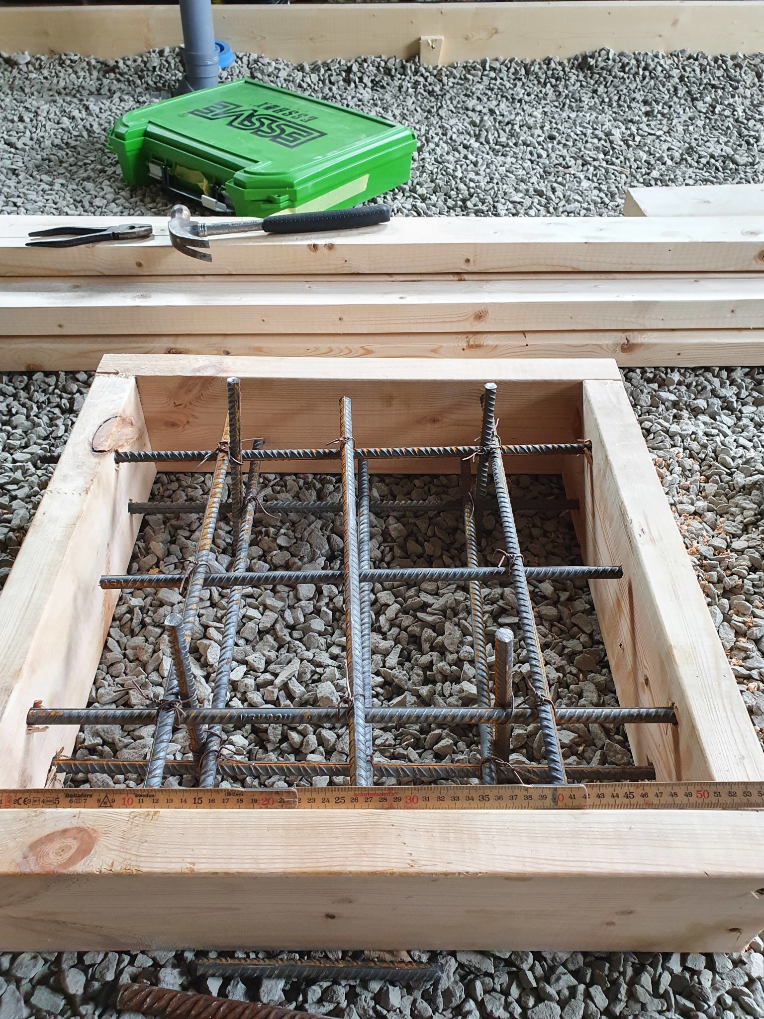
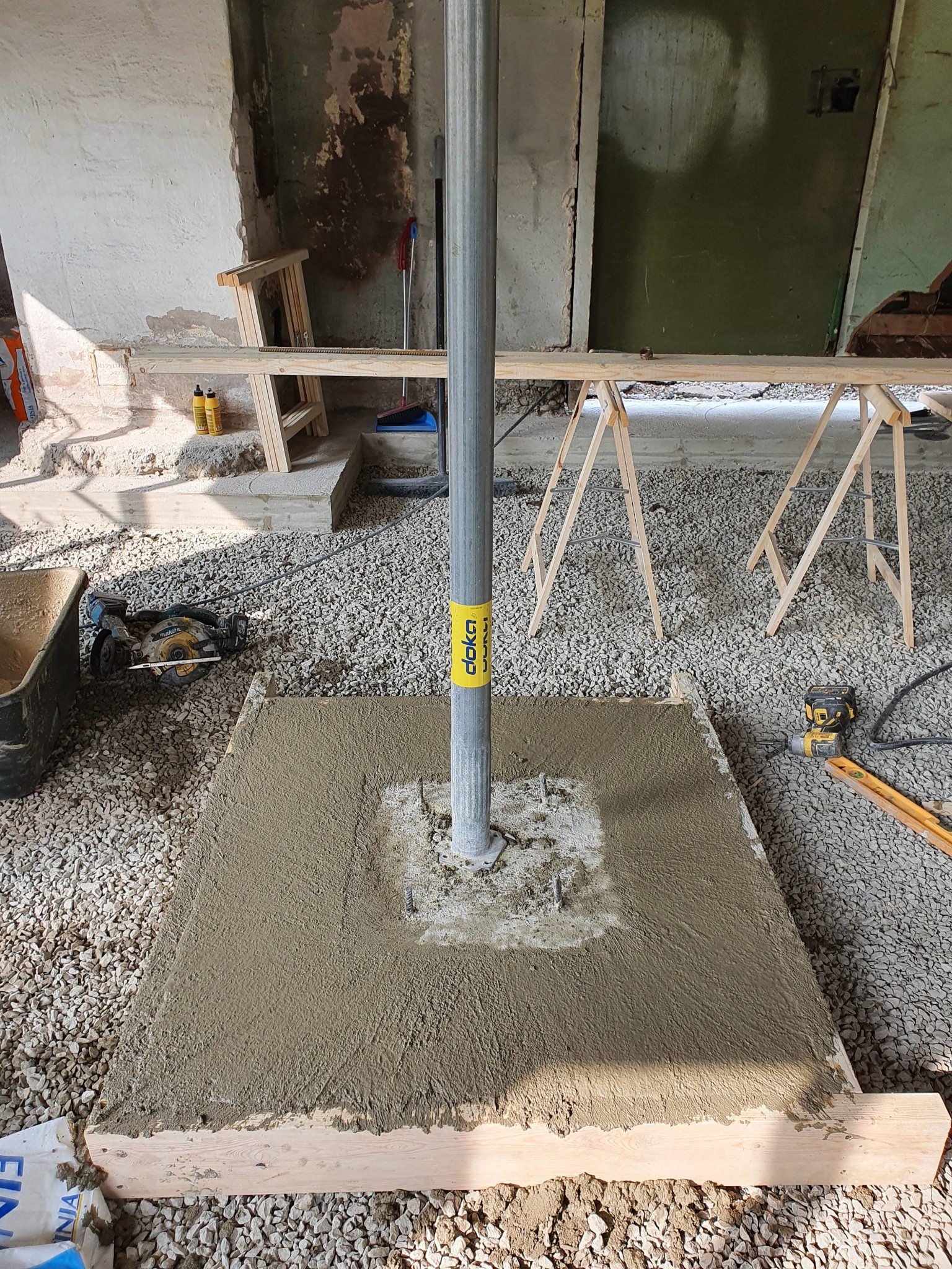
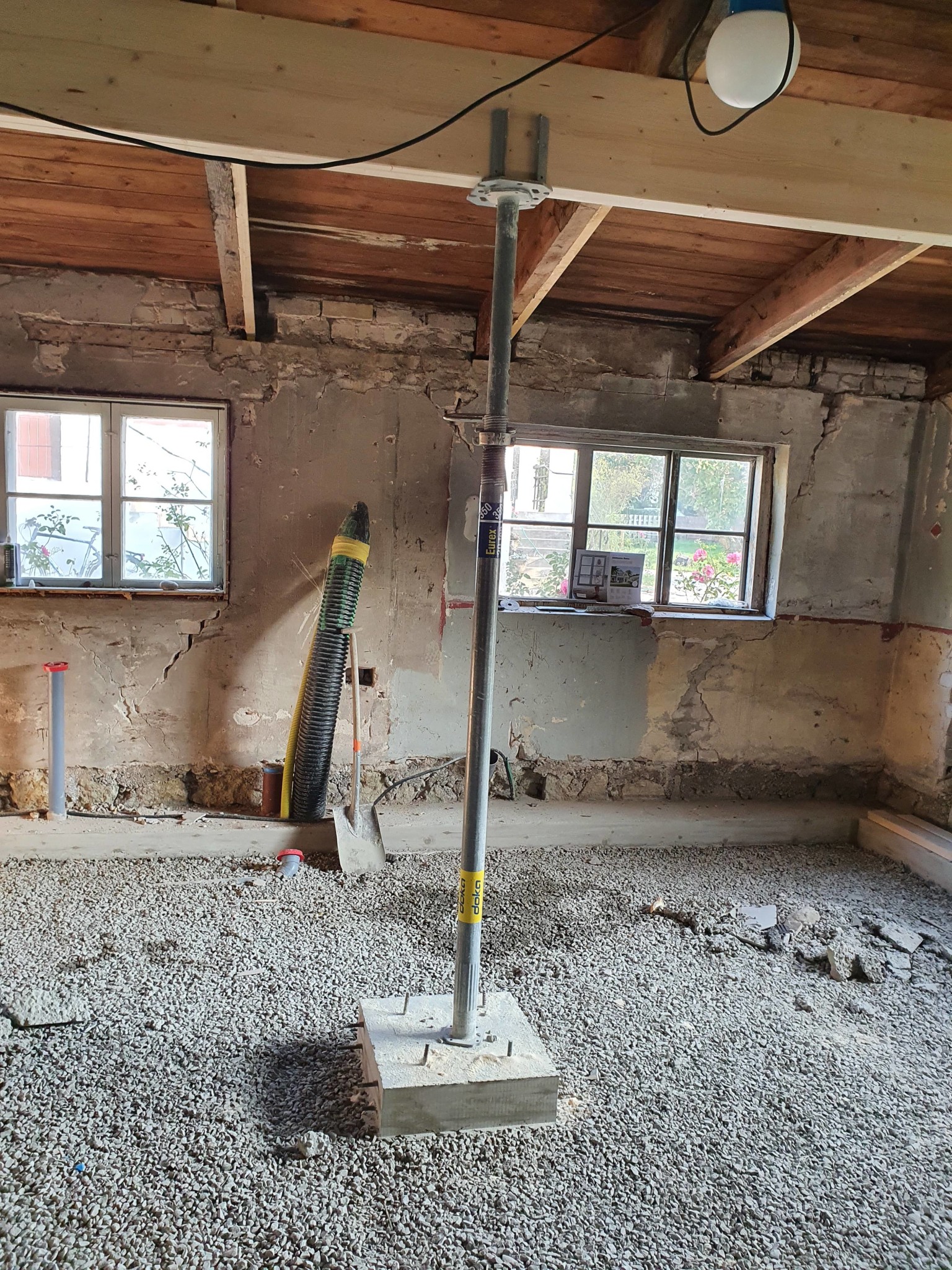
Today, the concrete foundation for the lone column is 510×510mm in size. So about 0.25 sqm.
The load on the ground then becomes 51kN/0.25~ 200kPa. The soil type is sand/moraine where we are. So it can handle between 100-200 kPa.
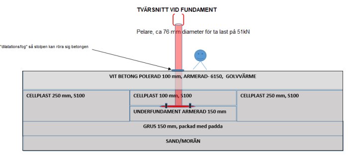
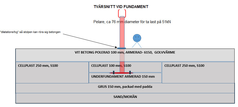
With a max snow load of 250kg/m2, we end up at 51kN. This last happened in 1987 where we live, so not unlikely.
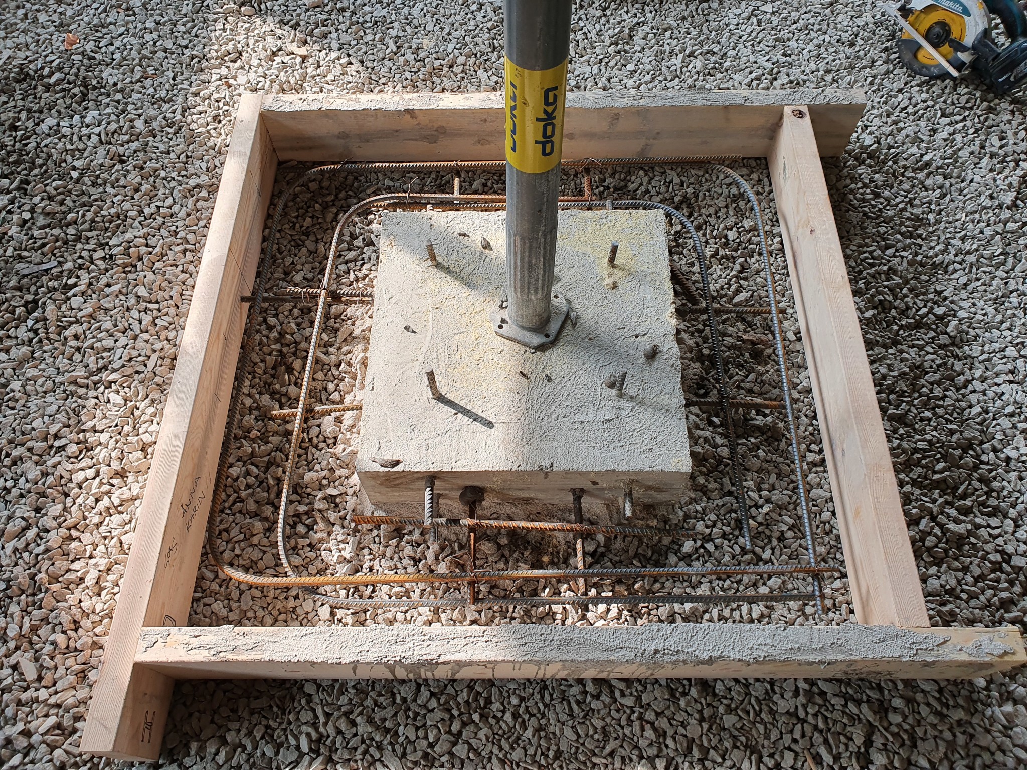
Should I pour a new foundation, like 1×1 m??
Then I'd land at 50 kPa on the ground.
It only takes an hour to drill some iron into the existing slab and nail a mold to cast a larger foundation. Costs little and provides better sleep in the future..
It only takes an hour or so to drill in some reinforcements into the existing slab and nail a form for casting a larger foundation.
Costs a little and gives better sleep in the future..
How many reinforcements from each side? I assume I'll continue with 12mm reinforcements that are in the existing one. The alternative is to demolish the existing and cast anew but maybe that's completely unnecessary?
A round steel pillar I think is a very good idea! It gives clear associations to early steel construction and is very fitting for the 1930s environment.
I think a round steel column is a very good idea! It gives clear associations to early steel construction and is very suitable for the 1930s environment.
We've discussed a bit at home and we're settling on a round steel column. Probably 76 mm diameter.
What's left is how we'll handle the foundation there. More opinions on iron/reinforcement/new mold are appreciated.
In the drawing, there's a 140mm slab with rebar mesh below and above. And 300mm eps underneath? How did you reinforce it? Or am I missing something? A bit tired in the noggin..
Are you going to cast the slab later?
Could you have moved the beam to the side of the window and embedded a steel column in the wall? Late now, of course.
On the drawing, it's a 140mm slab with reinforcement mesh above and below. and 300mm EPS underneath? How did you reinforce? Or am I missing something? A bit tired...
Are you going to cast the slab later?
Could you have moved the beam to the side of the window and embedded a steel pillar in the wall? Late now, of course.
12mm iron. The concrete is 140mm. I don't have EPS, but since the design program requires EPS, I assumed 300mm so it wouldn't become a bottleneck. Under the concrete, I have about 150mm of gravel compacted with a 450kg machine. The idea is that these foundations will lie under the new concrete floor that will be cast after EPS is laid everywhere, between 100-250mm depending on the place. Then 100mm of reinforced concrete with underfloor heating that will be polished according to HTC method. The whole purpose of this is to reduce the risk of cracks in the floor, which I want to be 100% crack-free.
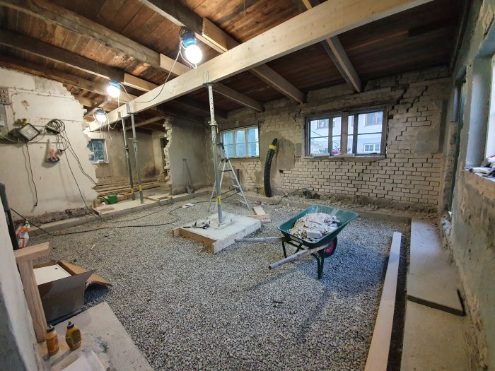
Here is our thought process regarding the entire floor construction. Sure, we could have cast the entire floor in one piece and still reinforced the concrete at critical areas. That would also allow us to insulate these substructures from below. But we believe this is the best solution to avoid cracks in the floor. Now the floor will be completely floating from the other constructions, which I like. The columns will emerge in the visible floor, without slabs and bolts.
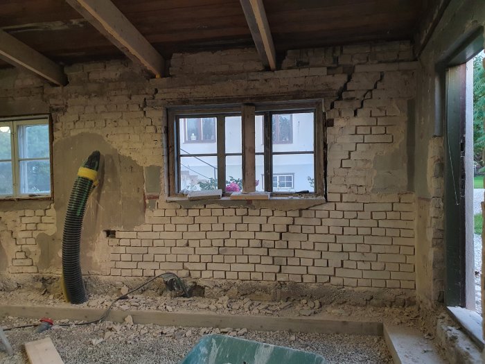
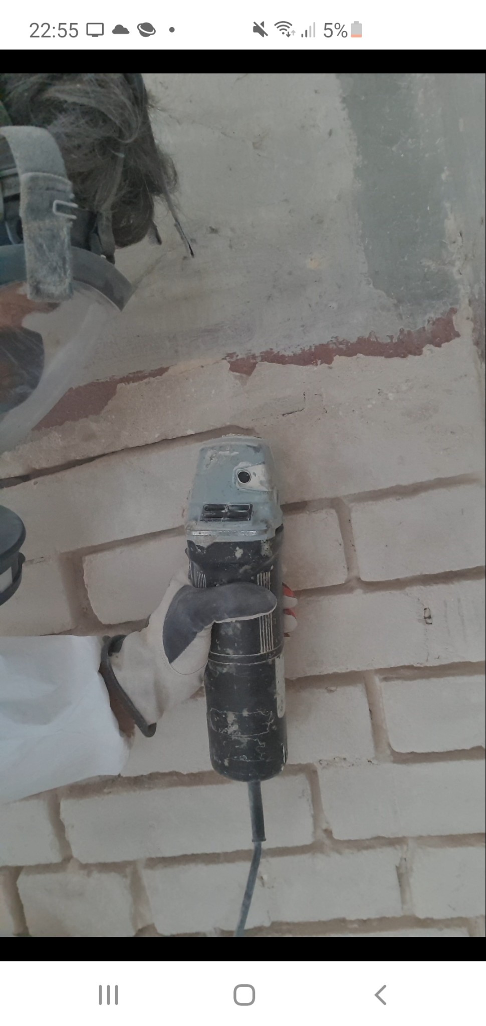
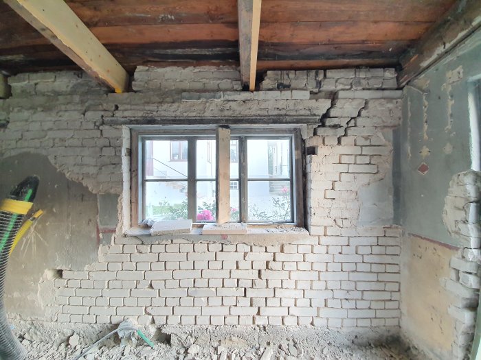
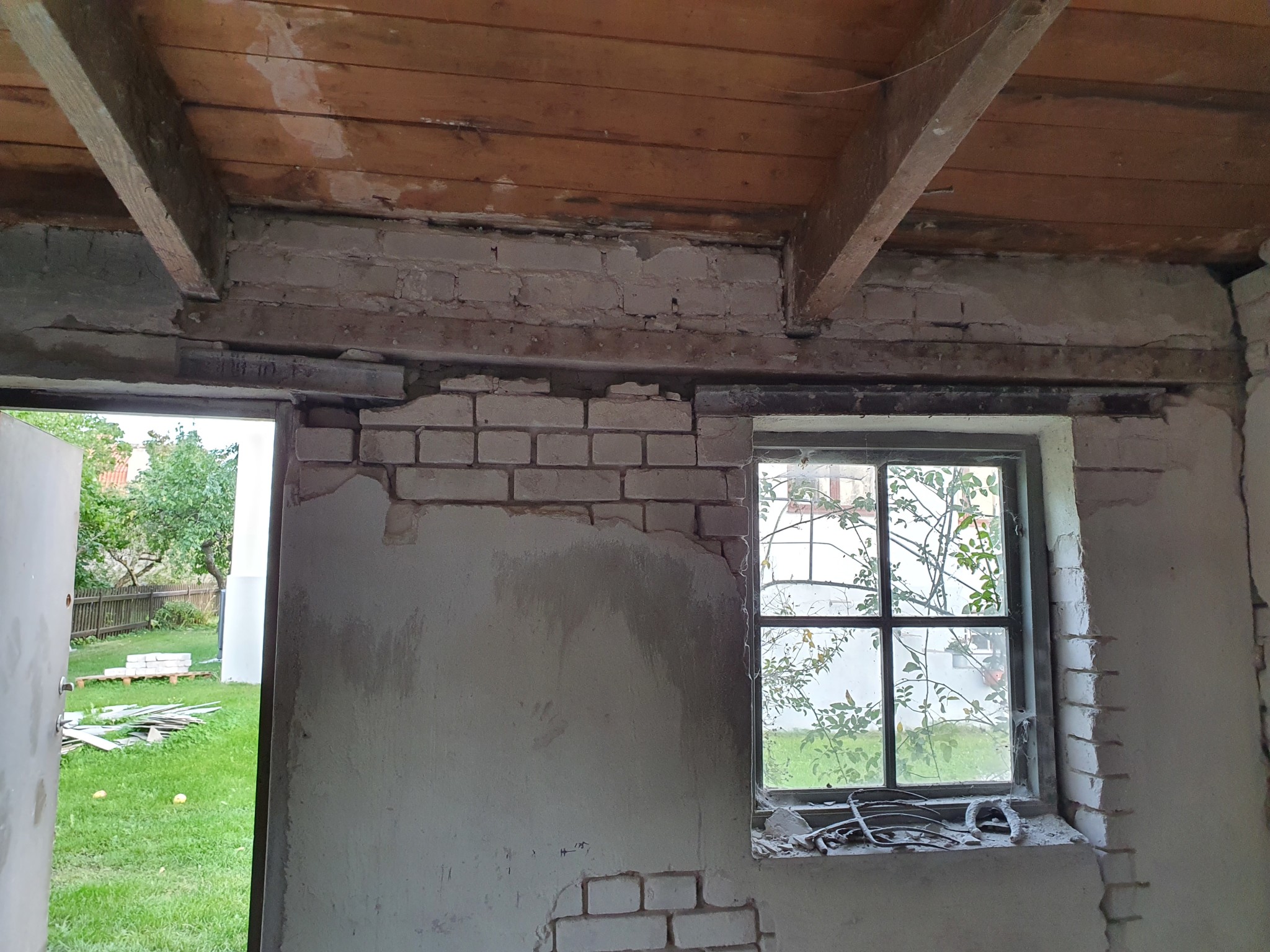
Update: milling/repointing of the brick wall that will be visible is currently underway. The part that will not be visible will be meshed and plastered. It is extremely time-consuming to chip/mill off old plaster, so one wall with visible brickwork will have to suffice, but it will look great when finished.
The forge is currently manufacturing KKR-columns that will be used as support for the glulam beam. Anchoring in the concrete foundations. It should be ready by Thursday next week. Once they're in place, we can finally focus on cellular plastic, reinforcement, and casting the floor!
The question is how to reinforce the masonry around the windows. The loads from the trusses are significantly lower than from the glulam beam. We are talking about around 5 kN per truss seat. A total of 9 trusses.
We have talked about the railway before. It turned out that there are two, one on the outside and one on the inside, on each window pane.
They are a bit rusty but still have good material.
Should I replace these or keep them? It's hard to see that a new U beam would be much better, indeed.
Is it correct to think about repairing the joints as I intended, to reinforce the wall? Or is that also insufficient?
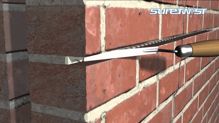
So, cutting out 30mm, inserting stainless steel as reinforcement, like stainless steel rebar 6mm L=500mm. See attached image of this reinforcement which is helical. I was thinking of doing the masonry with https://www.finja.se/produkter/gjuta-mura-putsa-laga/murbruk-b-for-kalksandsten
Don't want to rub salt in the wounds, but why wasn't a full-length beam ordered from the start?
Feels like you're now going to spend quite a lot of money instead of having consulted an engineer before you started?
The problem is probably ensuring which load the brick under the rail can handle, but couldn't you trace in vkr/kkr on the sides of the window opening or maybe cast an upright pillar?
Vi vill skicka notiser för ämnen du bevakar och händelser som berör dig.


Hallonbåten said:
On the drawing, it's a 140mm slab with reinforcement mesh above and below. and 300mm EPS underneath? How did you reinforce? Or am I missing something? A bit tired...