
96,858 views ·
36 replies
97k views
36 replies
Program for calculating truss constructions?

Are you going to have insulation in the roof? If so, consider designing the truss with this in mind. Here are some solutions from a couple of home companies.BME said:This is what I have been looking for. Can you help me figure out mine?
City: Karlskrona (Blekinge)
Roof type: Concrete tiles on swall 22mm
Span: 707cm between the outer edges of walls
House length: 770cm
cc distance 120 cm
Roof angle: 14 degrees
Eaves length: 40cm
I am trying to attach a sketch I made in the fine drawing program Excel.
Thank you so much in advance
https://www.borohus.se/standard-tillval/ (click on delivery description)
http://www.faluhus.com/files/KL-2004.pdf
and here you can see different truss tails Trusses Truss in Nässjö and Småland - Nässjö Takstolsfabrik AB - Truss Factory
HelloSnailman said:
Thanks for the good links. I plan to insulate the joists, that is, the flat inner ceiling.
A truss construction similar to the one NST has in their offer calculation image looks good.
I plan to use claws like NST alt.A Hope the pictures come with it.
regards Mattias
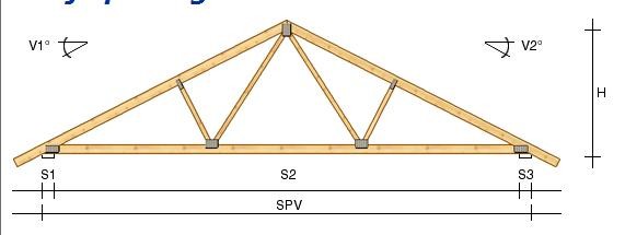
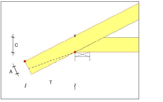
Hello BME! The program recommends the following dimension: 42x225, both for the forearm and the upper arms, based on the values you have provided plus the unfurnished attic. The type of truss is a truss (applies up to 27 degrees) with support posts in the form of a W inside the truss. What makes the timber strong is the long span and the roofing.
Ok, thank you for that.sommarbygge said:Hello BME! The program recommends the following dimension: 42x225, for both the underarms and the upper arms, based on the values you have provided plus the unfinished attic. The truss type is a truss (applies up to 27 degrees) with support posts in the form of a W inside the truss. What makes the timber substantial is the long span and the roofing material.
Is there any indication of how the W bracing should be mounted? That is, how close to the outer edges the outer braces should be placed, I assume the middle braces should go to the middle, see the picture in my previous post. When I look at the picture again, it seems that the outer legs should go to the middle of the upper frames, is that correct?
Best regards, Mattias
Hello BME! The program recommends the dimension 42x225 for the roof truss (upper arms and lower arm). The recommendation is based on the values you have provided plus the fact that the attic is unfinished. The roof truss is of the type truss framework, with support braces in the form of a W INSIDE the truss and fastened with nailing plates in the truss or nailed ON. These braces are usually of the dimension 45x95. You must, of course, obtain more information on HOW the actual truss should be assembled. Good luck!
The response you received from sommarbygge excellently demonstrates why one should avoid using ready-made calculation programs if they don't know what they are doing. The recommendation you received is highly questionable and not without issues. Just the fact that you haven't gotten an answer on how the braces in the W should be placed in relation to the spv. is one such issue. This should be discernible from the table included with the program.
To begin with, you should not use the outer dimension as the measure for spv. but the measurement between the inner edge of the walls + 50 mm on each side. The length of the rafter tails matters more or less not at all in this context. The slight opposing moment that can be obtained from these (and positively affects the dimension in the upper frame) is negligible (and if so, only on the short bit between the eave and the compressive brace).
Furthermore, one should calculate based on the standard measure of 1.2 m in cc, nothing else, as all timber and insulation are based on this measure, which is a multiple of the 3M system (3M = 30 cm). If this measure does not match the length of the house, adjust in the gable sections.
Secondly, you should not need 42x220 in the lower frame for load reasons. It is mainly subjected to tensile force. (Possibly the program designer made a general addition for accommodating mineral wool insulation.)
If the program says that these timber dimensions are the same for trusses with slopes from 14 to 27 degrees, I would claim without hesitation that the program designer knows nothing about static calculation. The higher the degree, the smaller dimension is needed in the upper frame. It will be, in other words, over-dimensioning to use this truss for a roof with a 27-degree slope.
As for your question about how the braces should be placed, usually, a W-truss assumes they should land at the third points of the lower frame. The brace (compressive) going up towards the upper frame should from there meet the upper frame at a right angle. The other brace (tensile) should go from this point on the lower frame and up towards the ridge.
If you are assembling it yourself with a joint in the lower frame (alternative is to use glulam beams and turn the truss into a standing truss, which will be easier for you and probably not more expensive either), i.e., the glulam beam will take the entire load, and the upper frame will be supported with vertical braces from this and can therefore be made quite weak in dimension, it should be placed midway between the walls. The upper frame should be similarly joined between the ridge and the compressive brace (closer to the compressive brace, how close depends on where the moment shifts after the compressive brace) if you cannot get long enough timber (but preferably be whole since it is subjected to both compression forces and bending moments).
Do not use nail plates over the joints either, but strips of 13 mm K-plywood p.b.s., nailed with galvanized square boat nails (oriented with opposite sides parallel to the wood grain), dim 60x43, in a 2-cut joint (i.e., the nail goes through from one side of the plywood to the other side), unlike nail plates and round anchor nails which give a single-cut joint (worse) and crushing in the wood under load. Nail groups should further be collected at both ends so that the largest opposing moment is obtained. (Particularly applies to a joint in the lower frame.)
If you're nailing it yourself, you should make a template of the first truss on a flat surface (i.e., you make a truss with the upper frame, lower frame, compressive and tensile brace, and then 'stack' the trusses on each other following this template during the nailing, before the assembly you then turn one truss at a time and nail from the other side before installation). And then you should draw out all centerlines in the timber parts so that they coincide at the meeting points. You should then nail the braces between the lower and upper frames so that the centerlines in these timber parts coincide with those you drew on the first truss, and then you can do it as they did before: a compressive brace is single (45x95), a tensile brace is double (2x28x120) and nailed on the outside of both the upper and lower frames and over the compressive one at the meeting point on the lower frame.
______________________
Byggaren
To begin with, you should not use the outer dimension as the measure for spv. but the measurement between the inner edge of the walls + 50 mm on each side. The length of the rafter tails matters more or less not at all in this context. The slight opposing moment that can be obtained from these (and positively affects the dimension in the upper frame) is negligible (and if so, only on the short bit between the eave and the compressive brace).
Furthermore, one should calculate based on the standard measure of 1.2 m in cc, nothing else, as all timber and insulation are based on this measure, which is a multiple of the 3M system (3M = 30 cm). If this measure does not match the length of the house, adjust in the gable sections.
Secondly, you should not need 42x220 in the lower frame for load reasons. It is mainly subjected to tensile force. (Possibly the program designer made a general addition for accommodating mineral wool insulation.)
If the program says that these timber dimensions are the same for trusses with slopes from 14 to 27 degrees, I would claim without hesitation that the program designer knows nothing about static calculation. The higher the degree, the smaller dimension is needed in the upper frame. It will be, in other words, over-dimensioning to use this truss for a roof with a 27-degree slope.
As for your question about how the braces should be placed, usually, a W-truss assumes they should land at the third points of the lower frame. The brace (compressive) going up towards the upper frame should from there meet the upper frame at a right angle. The other brace (tensile) should go from this point on the lower frame and up towards the ridge.
If you are assembling it yourself with a joint in the lower frame (alternative is to use glulam beams and turn the truss into a standing truss, which will be easier for you and probably not more expensive either), i.e., the glulam beam will take the entire load, and the upper frame will be supported with vertical braces from this and can therefore be made quite weak in dimension, it should be placed midway between the walls. The upper frame should be similarly joined between the ridge and the compressive brace (closer to the compressive brace, how close depends on where the moment shifts after the compressive brace) if you cannot get long enough timber (but preferably be whole since it is subjected to both compression forces and bending moments).
Do not use nail plates over the joints either, but strips of 13 mm K-plywood p.b.s., nailed with galvanized square boat nails (oriented with opposite sides parallel to the wood grain), dim 60x43, in a 2-cut joint (i.e., the nail goes through from one side of the plywood to the other side), unlike nail plates and round anchor nails which give a single-cut joint (worse) and crushing in the wood under load. Nail groups should further be collected at both ends so that the largest opposing moment is obtained. (Particularly applies to a joint in the lower frame.)
If you're nailing it yourself, you should make a template of the first truss on a flat surface (i.e., you make a truss with the upper frame, lower frame, compressive and tensile brace, and then 'stack' the trusses on each other following this template during the nailing, before the assembly you then turn one truss at a time and nail from the other side before installation). And then you should draw out all centerlines in the timber parts so that they coincide at the meeting points. You should then nail the braces between the lower and upper frames so that the centerlines in these timber parts coincide with those you drew on the first truss, and then you can do it as they did before: a compressive brace is single (45x95), a tensile brace is double (2x28x120) and nailed on the outside of both the upper and lower frames and over the compressive one at the meeting point on the lower frame.
______________________
Byggaren
Here's how I would have done it (I've done it once for a garage), I would go to the library and borrow the truss book, check if they have a truss that fits in the tables, then I would check which snow zone I had, not in the book, (as it might be a little old) but in the latest (They have recently changed) for example here: http://www.takstolsfabriken.se/doc/snozon.pdf
In the truss book, it states exactly how nail plates/anchor nails should look for each joint.
Then I would follow the instructions exactly.
In the truss book, it states exactly how nail plates/anchor nails should look for each joint.
Then I would follow the instructions exactly.
Click here to reply