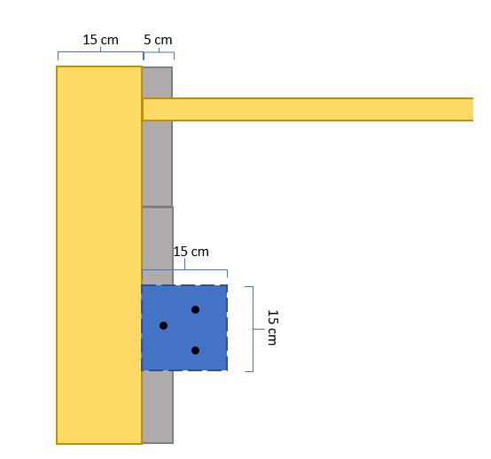
I believe the floor joists rest on a ledge and that the sill is only 15 cm.
I'm thinking of doing this:
From above:
- Wondering if I really need three rebar in a footing that is 15x15 cm? Should I make the footing larger or will 15x15 be good? The pillar is 9x9 cm.
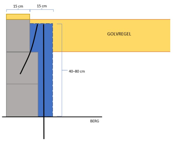
From the side:
- is it good to bend the rebar (I think a 5 cm ledge is too little to attach a rebar). I want the footing to be secured against "falling out/off" from the foundation.
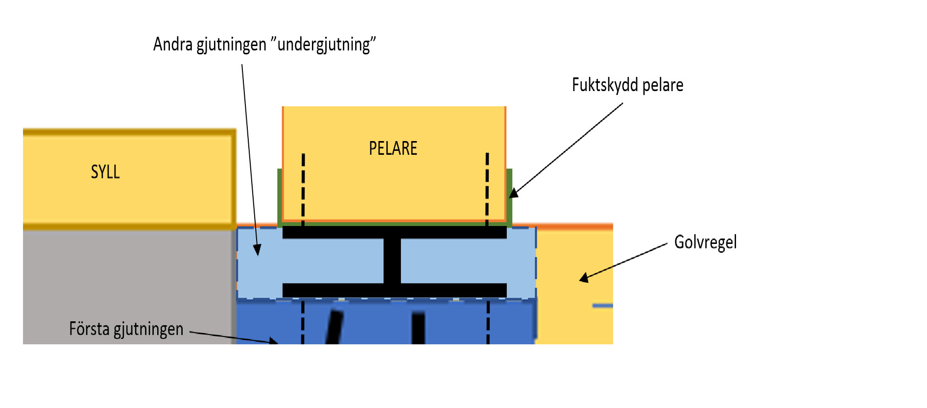
Detail fitting:
- I'm thinking of placing some type of paper between the fastening metal and the pillar. The bottom edge of the pillar will be level with the top edge of the floor joists. I will then have to cut out the floor chipboard around the pillar.
I would have made the footing a little larger, ~200x200. Partly so you get a little more concrete on the inside of the foundation wall and it becomes easier to drill into the rock. At the joint between concrete and rock, you should protect the rods with, for example, protectorbinda or choose stainless steel rods. Make sure you have ~40mm concrete outside the rods. Two rods, d12mm, in the footing that you drill into the rock are sufficient. If you want more, you don't need to drill them in, just cast them into the footing. To connect the footing with the foundation wall, you could drill in C-hooks, cc200+1st, d=6mm, in the wall that enclose the reinforcing rods.
Perfect! Then I'll make it 20x20 and skip the angled iron.
I'm not really following how I should be able to drill the C-bracket into the foundation wall. It looks like it would need to be a very large drill bit. I don't think I quite understand how it should be used.
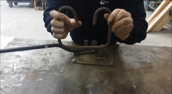
The C-bar can be bent like a U; you should not make an end hook as shown in the picture. The bumps in the picture I attached only symbolize the end of the iron, not a hook.
Stainless steel rebar is very difficult to obtain and very expensive.
The bindan (protector pad) I'm not quite sure how to use. Should I wrap the steel at the transition between rock/concrete? I think the steel will just rust further down. Or should I wrap the entire steel that's in the rock? Then I would have to drill a larger diameter hole.
Can't I just drill, for example, 20 mm and fill with concrete and then press down the rebar? That way the steel is enclosed by 4mm. concrete.
The question is really what the roof (60 m2 at the opening) weighs:
Opening 6-7 m x 8.50 m
Studs cc 120
Insulation 25 cm
Ceiling (single plasterboard) mounted on slatted panel
Tongue and groove sheathing in the outer roof 22 mm
Roof felt
Opening 6-7 m x 8.50 m = 60 m2
Roof beams cc 120 type Huntington 6 pcs x 8.5 m x 6.2 kg = 316.2 kg
Insulation Paroc 220 mm stone wool = 366 kg
Ceiling (single plasterboard) mounted on sparse paneling 552 kg
Tongue and groove board in the outer roof 22 mm = 627 kg
Roof felt 3 layers = (3.6 kg/m2) 648 kg
Sparse paneling that the plasterboard rests on estimated at 100 kg
Nails estimated at 100 kg
Outer paneling around the eaves estimated at 100 kg
316
366
552
627
648
100
100
100
_____
2,809 kg
If each prop from Hornbach can support 1800 kg, I should be able to hold up the roof with two of them (2x1800=3600 kg).
I may not need to add that I shouldn't perform the deviation under snow load.
Snow zone 2 = 200 kg/m2
60 m2
60x200 = 12,000 kg
According to my calculation, component by component, the delimited part (60 m2) of the roof weighs 2,800 kg, or just 46 kg/m2. It can be noted that some allowances are made in calculations for snow load.
Partly, it is a question of what the post should withstand, and partly where the biggest loads occur. I would probably place a post under each roof beam and put a strong plank, preferably 45x220, on top of them. I recall that the glulam beam, including snow, had a distributed load of about 13 kN/m, which totals 78 kN for a 6 m beam. If you have 6 posts, that becomes 13 kN/post, i.e., about 1300 kg per post with snow. I assume you are not doing the job with snow on the roof? With 6 Hornbach posts, you are on the safe side in any weather. I no longer remember what the loads were without snow, but I think it is more important that the post stands correctly, even if it means some "overcapacity." Then I wonder, wouldn't it be cheaper to rent?
I believe that the snow load today should correspond to a maximum value over a fifty-year period. But I can also note that snow loads have been significantly increased since BABS 1960 (the building code at the time) as a result of accidents that have occurred. Adaptation to local conditions has also improved.
Vi vill skicka notiser för ämnen du bevakar och händelser som berör dig.


")