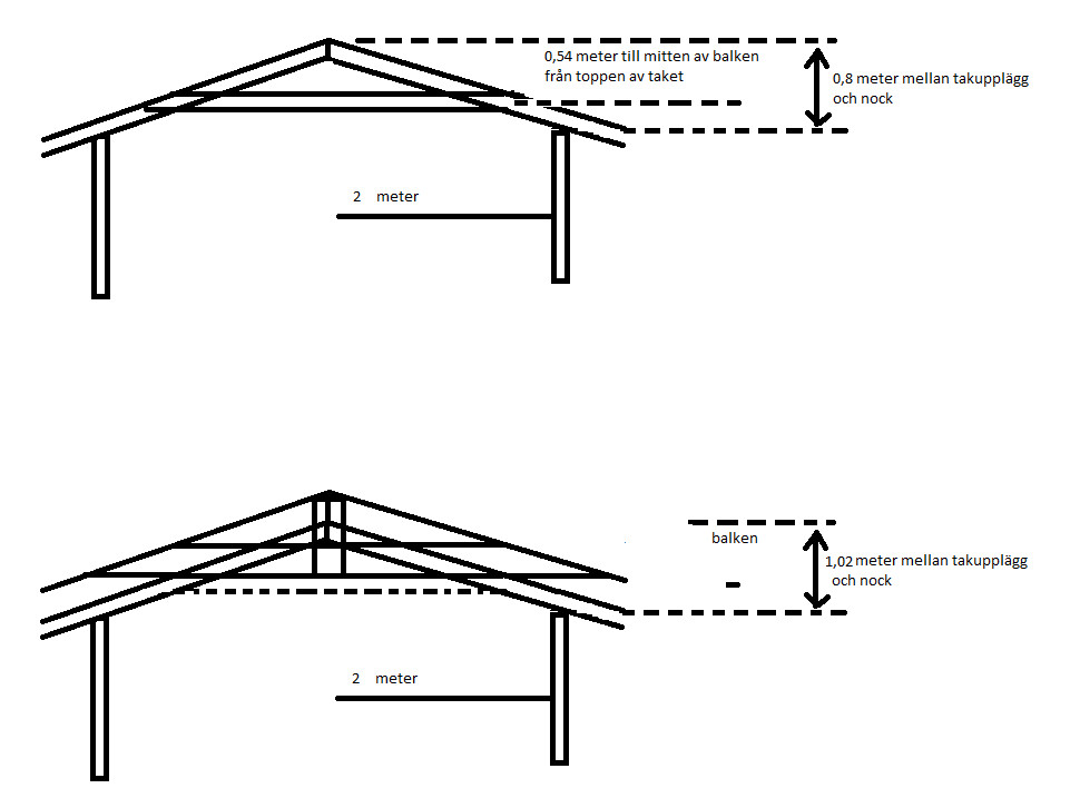
I have an old log cabin with a slightly low ceiling. The rafters are dimensioned at 62.5*150 mm and have dimensions according to the picture. The span is 4.1 meters, the height between the support and the top of the roof is 0.8 meters. The horizontal beam is at a center distance of 0.54 meters from the top of the roof.
I plan to remove the roof decking and put a 220 mm joist on top of the rafters, nail new decking, and nail nail plates between the rafters and the 220 mm joists. The new horizontal rule will also be 220 mm. It should reasonably be possible to raise the horizontal rule somewhat, but the question is how much? I can also add a vertical joist from the ridge, which should strengthen it somewhat.
Does anyone have a calculation model for this type of rafter? It's only about 7 rafters, so I can use expensive materials if it gains ceiling height.
The cabin is located in snow load zone 3kN/m2, it feels like the original rafter is a bit weak, but the cabin has stood for 60 years, so it seems to work.
The rafters are calculated as beams. The collar beam (the horizontal beam) is subjected to tensile forces, and the attachment to the rafters is important to ensure it can really handle the tension. Your 62.5x150 joists are equivalent to 45x170 in bending stiffness, so they're not that bad.
I would consider adding an extra log layer on the outer walls and increasing the roof pitch significantly. This has several advantages, not just increasing the ceiling height. Without going into a long mechanics explanation, you can use slimmer lumber when the pitch increases. To calculate the trusses, you need to know the roof pitch. A rough estimate with some guessed values leads me to believe that the current situation is on the edge. However, there is no risk of the roof collapsing.
I've been looking for an example calculation online for a truss but haven't found any, so I'm trying to reason a bit myself...
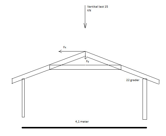
See the image below. The snow zone is 3KN/m2, and the house has a span of 4.1 meters, with 1.2 meters between the trusses, and the roof angle is 22 degrees.
I think the design load is 1.2*4.1*3 = 14.8 KN. This load is evenly distributed over the truss, but for simplicity, let's think of it as a point load at the ridge of 15 KN.
The truss should transfer the purely vertical load to another vertical load on top of the walls. We break down the total load into force components. The initial 15 KN load also results in a horizontal Fx force of Fx=Fy / tan 22, where 22 is the roof angle.
Since the wall cannot handle horizontal forces, we add a collar tie to carry Fx (tension, not bending) = 37 KN ( =15KN/tan(22) )
Intuitively, I understand that the construction becomes weaker the closer to the roof I set the collar tie, but I don't know how it should be included in the calculations. Anyone have suggestions?
It is the compressive strength that should be so large, and it does not take buckling into account.
A lot of calculation is required to determine how much load a beam can handle; it is not as easy as you show above. Just the fact that your calculation gives a value close to 100 times your load should set off alarm bells
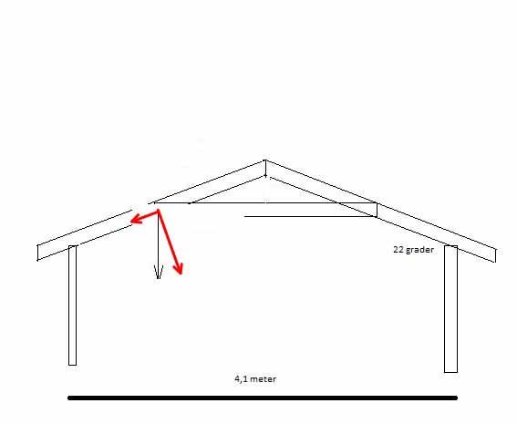
The calculation process involves examining each rafter individually. In this case, we can disregard the eaves. They only affect the support reactions. Snow load is calculated on the horizontal plane. Since the slope is 22 degrees, we can use the characteristic load of 3 kN/m2. (There are form factors to consider) The total snow load on a truss is 2.05*1.2*3=7.38 kN. Then comes the roof's own weight, which we assume to be 0.5 kN/m2. Since the rafter length is 2.05/cos 22°=2.2 m, the self-weight is 2.2*1.2*0.5=1.32 kN. The total truss load becomes 7.38+1.32=8.7 kN. The component perpendicular to the rafter according to the image below is 8.07 kN. This is what determines the dimensions of the rafter.
The simplest way to determine the tensile strength for a stud is to look in the Wood Guide. In the tables for different types of structural timber, there is information on the allowable tensile normal force (Nt). A 45x95 C 24 can handle about 40 kN.
A lower roof slope gives lower tensile force but higher bending moment and vice versa.
Click here to reply
Vi vill skicka notiser för ämnen du bevakar och händelser som berör dig.