I want to address horizontal force in the collar tie with the following construction.
I plan to mount an HEB 100 or 120 beam in a concrete wall built of formwork blocks, the wall is 190mm thick.
The beam is fixed by attaching it to the wall with two brackets secured with an expander or through bolts. I wonder how much horizontal force an HEB 100 and 120 can take up before the deflection exceeds 20 mm.
Can someone point out the appropriate formula to use? Even if someone gives me a formula, I would like a statement
on how much load this structure can take. See attached image.
The beam is a total of 3500mm, 1500mm is fixed in the wall (from the wall top and downwards), and the beam extends 2000 mm above the wall and should be attached to the collar tie to take up horizontal forces in the collar tie.
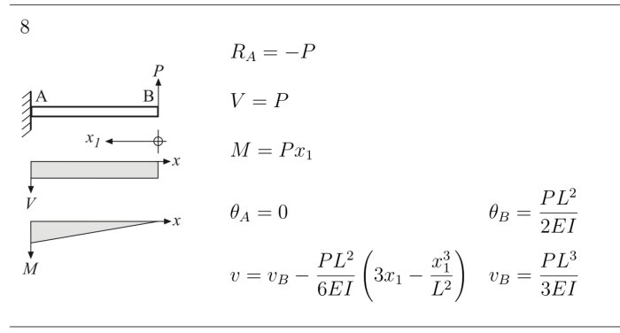
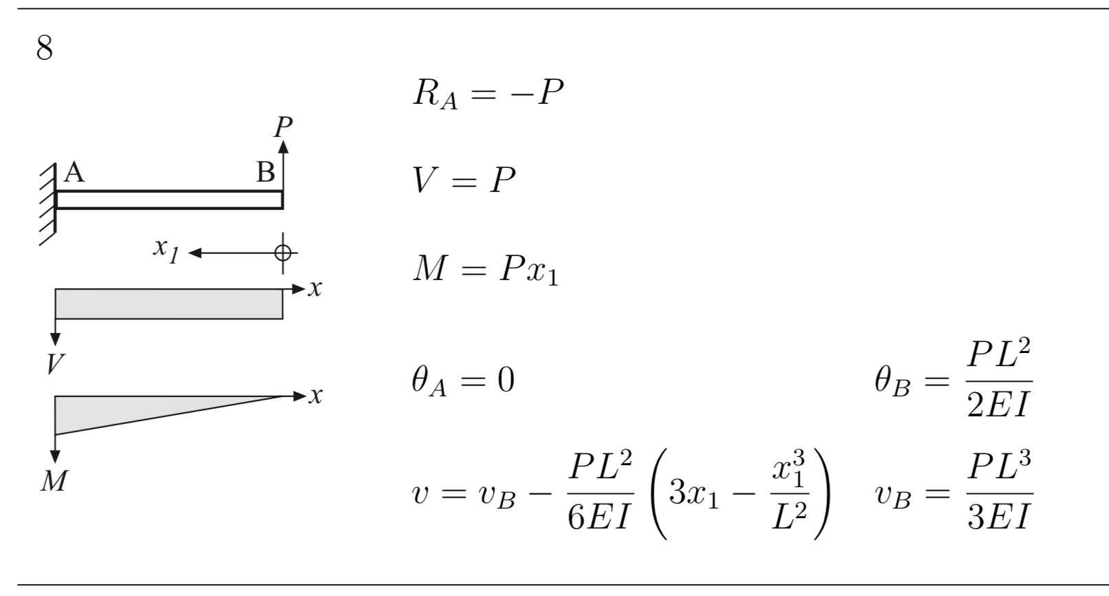
Assuming the beam is rigidly fixed to the wall, it can be seen as a cantilever beam with a length of 2000 mm. For a point load at the end, deflection is calculated using the following formula (v_B).
P is the force, L is the length, E is the modulus of elasticity, and I is the moment of inertia.
The modulus of elasticity is approximately 200,000 MPa for steel. The moment of inertia for standard cross-sections can be obtained from manufacturer tables or from formula collections (e.g., the one linked).
For HEB100 and HEB120, the moment of inertia is 4.5E6 mm^4 and 8.6E6 mm^4 respectively when they are oriented so that the load acts perpendicularly to the flanges.
To achieve a deflection of 20 mm with HEB100, a force of 20 x 3 x 200,000 x 4.5E6 / 2000^3 = 6.8 kN is needed. With HEB120, the force becomes approximately double.
Thank you for an educational response! Interesting that it so to speak becomes twice as "strong" if one may express it that way to go from HEB100 to HEB120.
Assuming the beam is free between the stirrups, that it is oriented in its stiff direction and that the force is applied at the top, I get a deflection of 20 mm at the top with a force of 4.0 kN for HEB100 and 7.8 kN for HEB120.
Thanks for an educational answer! Interesting that it becomes, so to speak, twice as "strong" to go from HEB100 to HEB120 if I may express it that way.
Yes, to be precise it becomes twice as stiff (deformation per unit load). For bending specifically, increasing the height or otherwise getting more material far from the cross section's neutral plane has a significant effect. To bend the beam, material far out needs to stretch more (resisting with greater stress while also increasing the lever arm to the neutral plane). So there's a double effect.
The strength, which we can define as the load the beam can carry without damage, differs less between the two cross sections, about 60% higher for HEB120 compared to HEB100.
Then you need to calculate the stress in the beam and compare it with a strength value.
For the same load case as before, the (maximum) stress is calculated as the bending moment divided by the section modulus. The section modulus can be found in the same tables as the moment of inertia.
If you choose the yield strength (the limit for permanent deformation) as the strength value and assume that it is steel S235 in the beam, the yield strength is reached at a force of 10.5 kN for HEB100 and 17.0 kN for HEB120.
When designing buildings, standards that include safety factors are used, which results in a lower allowable load.
Click here to reply
Vi vill skicka notiser för ämnen du bevakar och händelser som berör dig.
Hammarens kompis said: