I understand the problem.
The I-beam in my picture was divided into three equal parts that were welded together lying on the concrete slab. In this way, we could carry the beam into place by hand.
If we had used steel, I would have dared to do it like you. As I can calculate the weld and also trust its strength. Splicing a wooden beam is not something I learned how to do from someone knowledgeable at school/outside. Therefore, I don't dare to use it in practice.
But is it a pulling load or? If it's just weight from above then it shouldn't be a big deal to have a support with a joint, I guess? I'm mostly thinking that 16m long beams are quite "uncommon" unless you're going for purely industrial constructions. Just curious.
I am also curious, it would have saved us at least 20,000 just for the current project. But my knowledge extends to needing a moment-resistant joint. That is, a joint that transfers moment between the different beams. According to what I've read, such a joint should be placed where the moment is minimal. Because it is difficult to fix a moment-resistant joint.
I know where the moment is minimal. But I don't dare to risk placing something weak in a load-bearing structure, as I might have missed something.
Finding a crane truck that can legally transport 16m will be hard for you.
Why must they be exactly 16m if it is not for a 16m long room without pillars?
There are steel trucks that deliver 24m goods with a crane. But then you have to succeed in getting such a beast onto the site and also close to where it is going up. But managing to hire such a truck probably requires some serious persuasion.
Regarding the crane truck, my supplier said the same thing as you said. He could solve it by renting a separate crane truck.
For reasons, see post #28.
I'll look into whether I can manage the steel truck. I'm usually good at persuading, or at least I try to convince myself of that haha.
Probably to avoid joints and thereby an unnecessarily large beam. The original poster has described that the beam rests on three supports; a joint over the middle support would significantly diminish the utilization of the beam's strength, which would result in a larger dimension to compensate for that degradation.
It's quite dangerous to generalize like that. With a continuous beam, you simultaneously get a large top-side moment that you don't have with a split beam, and you introduce a risk of buckling over the support if you don't consider it. Then I assume that an engineer has dimensioned the beam, and then it's the conditions from them that apply. I can't imagine it has been calculated as one continuous beam. It's important that the joints are placed where they are accounted for in the calculation.
It is quite dangerous to generalize like that. With a continuous beam, you also get a large top moment that you don't have with a divided beam, and you introduce a risk of buckling over the support if not considered. Then I assume that an engineer has dimensioned the beam, and then the conditions from that are applicable. I can't imagine it is calculated as a single continuous beam. It is important that the joints are placed where they are included in the calculation.
I am the engineer. I have calculated the beam as a single 16m beam resting on 3 supports. The reason I did it this way is that I cannot dimension joints in wooden beams (newly graduated). I know they should preferably be placed at moment zero points. But can you trust that in practice? Have you dimensioned such joints?
Splicing a beam over a support is something I've seen countless times in all possible dimensions and it's always done the same way.
That is, 2 beams on each side and glue-screwed.
If there is limited space, steel plates are used.
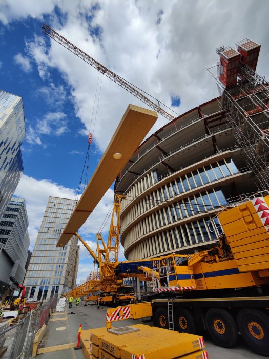
Nothing to do with the matter. Just a nice picture of glulam
I am the designer. I have calculated the beam as a single 16m beam resting on 3 supports. The reason I've done this is because I can't dimension joints in wooden beams (recently graduated). I know they should preferably be placed at moment zero points. But can you trust that in practice? Have you dimensioned such joints?
I have indeed done that but usually avoid it. Placing the joint at the moment zero point is done in what's called a gerber joint. It should then carry high shear force instead of high moment. However, the moment does not become zero because the moment zero point moves when the load moves.
Since you have very large beams it indicates that you have very large loads. Skip the joints for simplicity is my advice, or bring in an experienced designer. There's so much that can go wrong if you assume for example wrong bracing of the top/bottom of the beam and also in the way that you end up with a heavily over-dimensioned beam if you calculate with too little/no bracing.
Splicing a beam over a support, I've seen countless times in all possible dimensions, and it's always done the same way.
That is, 2 beams on each side, glued and screwed.
If there's little space, metal plate is used.
Nothing to do with the matter. Just a nice picture of glulam [image]
I'm setting it as a goal to learn how to splice wooden beams soon.
Glulam is really beautiful! Thanks for the picture.
I have indeed done so, but usually avoid it. Placing the joint at the moment zero point is done in a so-called Gerber joint. It should then bear high shear force instead of high moment. However, the moment does not become zero since the moment zero point moves when the load shifts.
Since you have very large beams, it suggests that you have very large loads. Skip the joints for simplicity's sake is my advice, or bring in an experienced engineer. There's so much that can go wrong if you assume, for example, the wrong bracing of the beam's top/bottom edge and also in the direction that you get a significantly oversized beam if you calculate with too little/no bracing.
Thank you, Witten! I will follow your advice and skip the joints/bring in a consultant who can fix it.
Then I will learn to do this myself, setting it as a goal for myself.
Do you have any sketches/drawings of how the construction is planned?
I only have A-drawings from the architect. I have only managed to sketch on paper when it comes to the K-drawings that I am going to create.
I am thinking of making the intermediate support in insulating Leca blocks. The rest of the frame in wood, except for the slab which may be 120mm btg, reinforcement: centered 10150.
Snow load: 1.5kN/m2 (characteristic)
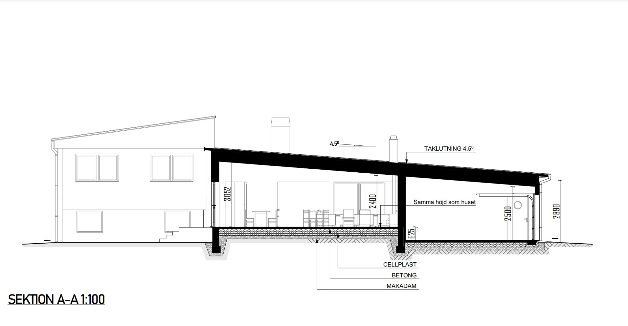
Attached is a section from the architect, (the span is 6.2+9m).
I only have A-drawings from the architect. I've only had time to sketch on paper when it comes to the K-drawings that I will make.
I'm thinking that the intermediate support can be made of insulating Leca blocks. The rest of the frame in wood, except the slab which might be 120mm btg, reinforcement: centered 10150.
Snow load: 1.5kN/m2 (characteristic)
Attached is a section from the architect, (the span is 6.2+9m).
Nice, where in the country will this be located?
Do you have any plans to look at too? 9m is a hefty span. Is there no alternative support for the roof?
Based on the section, the issue of tipping over the support is solved without problems, however, it can certainly become a bit challenging with the bearing pressure over the wall.
From the section, the issue of tipping over the support is solved without any problems, though it can certainly be a bit challenging with the support pressure over the wall.
Support force - exactly as you say. Therefore, we will use Leca blocks 300 or similar as the middle support. Then it becomes a large area for the beam to rest on (300x90mm).
Nice, where in the country will this be located then?
Do you have any blueprints to look at as well? 9m is a hefty span. Is there no alternative support for the roof?
Thank you!
Just outside Hässleholm (Skåne).
I will definitely take a look, I don't want to miss this. I love working on large spans.
Unfortunately, there is no alternative support. The owner is determined and has coordinated with the architect about this.
Vi vill skicka notiser för ämnen du bevakar och händelser som berör dig.