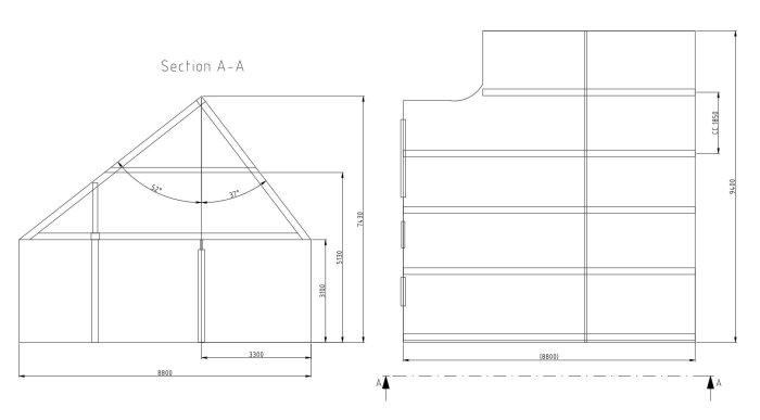
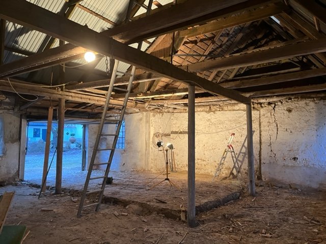
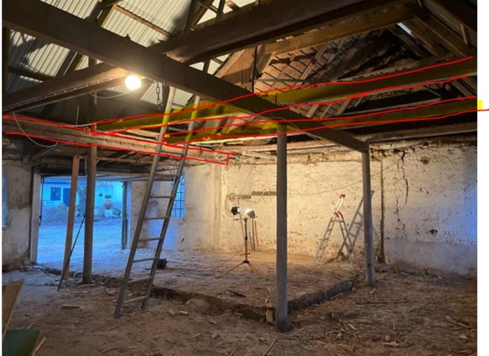
I have an old farm building that previously functioned as a garage. To meet fire safety requirements, there was previously a box in this larger section with double plasterboard. My plan is now to utilize the entire space for a garage, and I would like to clear it to achieve a higher ceiling height, among other things, to be able to install a car lift.
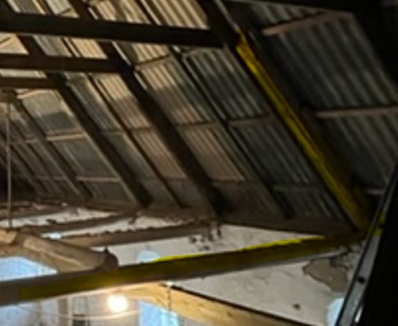
The roof material is asbestos-cement sheets on the right side and metal on the left of the ridge.
The plan:
- Dig out and cast a concrete slab
- Exchange the roof trusses in a suitable way to achieve high ceiling height inside
- Insulate the roof, install a ceiling that meets fire protection requirements
- Shield off other spaces in the attic on both sides, build up with two triangles, fire protection.
- Plaster the interior walls
- Heating system
One way might be to replace with a ridge beam.
We have a span of 9.4m, I can imagine 3 supports. I am sure that the roof trusses as they look today need to be adjusted possibly replaced (build new ones between the existing) to fit such a change.
Questions:
1. What alternatives are typically available to exchange and clear when it looks according to my conditions
2. Even if the roof trusses do not load the walls, is there a risk that the walls will move, they might need something to connect them side/side? (like it is today) These are old clay brick walls.
Other
I must study myself what the requirements are and how one should do to fulfill fire protection requirements but if you have any tips e.g. fiberboard + 1x plasterboard is okay, I would gladly receive them.
It's quite a complex task ahead of you. If you don't need the intermediate floor across the entire length of the house, I would focus on removing the middle part of it, but keep the row of columns that support the struts to the roof truss. Insulate up against the collar beam.
I can add that we are located in southern Skåne, snow load 1, wind load 26.
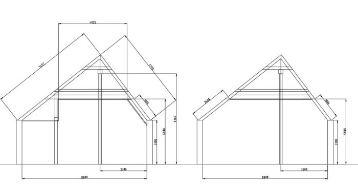
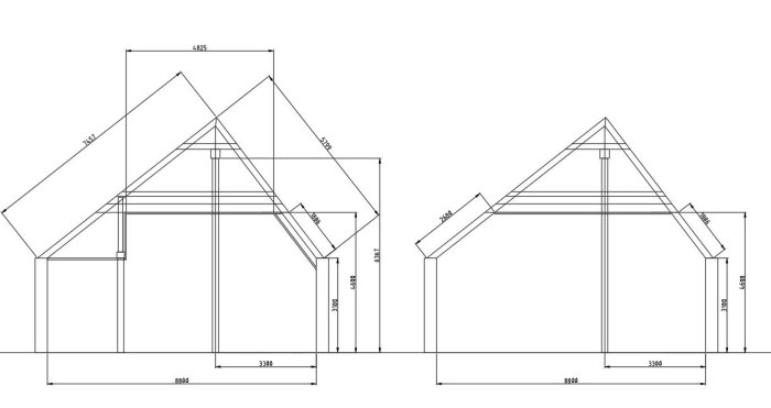
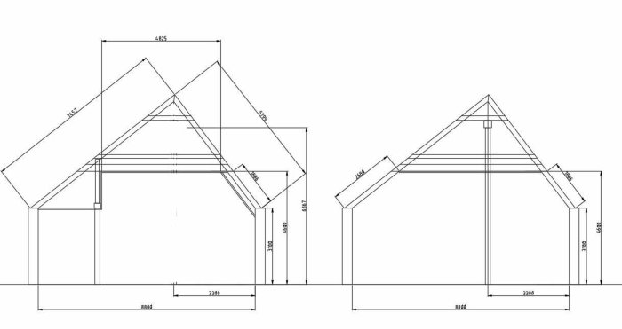
If I interpret your response correctly, we have something similar to the left sketch.
I have added an extra beam partly because I think they should be sturdier than the existing ones, and partly because I can set them at the right height so that a framework for gypsum cladding doesn't need to be shimmed.
The sketch on the right is my original idea, but there is enough space for lifting even if you build according to the proposed principle.
It should look roughly like the picture on the left. Most collar beams are oversized. They are usually only subjected to tensile forces. Preferably, a collar beam should not be moved vertically. However, there is nothing stopping you from adding an additional one.
Okay, as I interpret your response, the change does not require the installation of a ridge beam, which makes it easier.
The beams I wish to remove were part of a floor structure and in the past, the load was heavy on all these lofts.
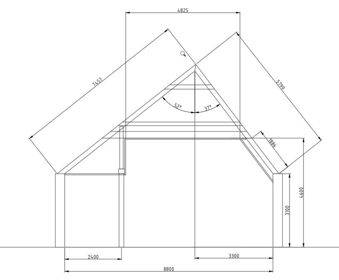
My main concern is about what measures might be required if we proceed with the sketch below.
Is the collar beam in the truss sufficient to prevent the walls from being subjected to an outward force?
Sure. What you remove does not affect the truss function at all as far as I can understand (if you've drawn it correctly). The collar beam also helps to reduce the dimensions of the rafters. Therefore, it should not be moved.
Certainly. What you're removing doesn't affect the roof truss function at all as far as I understand (if you've drawn it correctly).
Are you sure about that? If I haven't completely misunderstood, the beams that "hold together" the walls are being removed (the floor frame that forms the large triangles in the current trusses). Without support on the side with the steep roof, it appears there's a risk of forces pushing the wall outward. It's "just" the bending resistance in the lower part of the roof beam (the collar beam? I don't know the terminology properly...) that resists (besides the wall, of course). Whether the forces are at a level that needs concern, I'm not brave enough to judge.
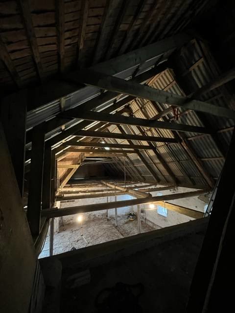
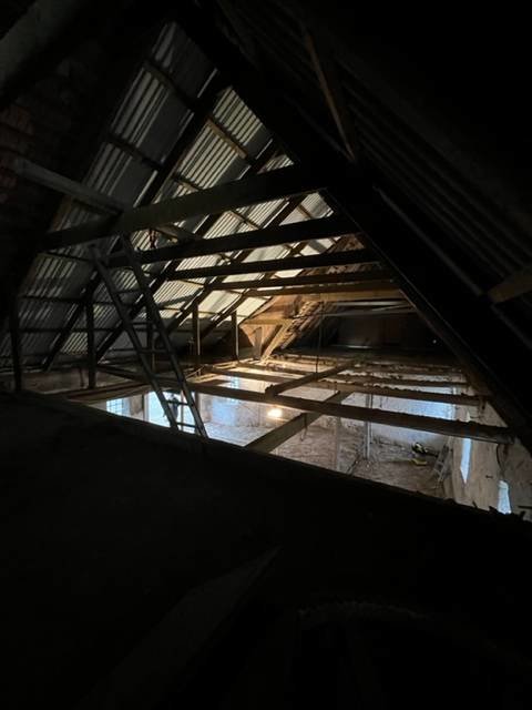
The tie beams remain and serve precisely the unifying function. The remnants of the old intermediate floor do not have this, as can be seen from the pictures and drawings.
I misunderstood what the "hanbjälklaget" was, so ignore my reference to it...
How do you see that the old floor joist doesn't have a cohesive function? Don't you think that those beams are connected to the longitudinal beam (along the wall) and thus the trusses? The corresponding constructions I have investigated were connected there and created a large supporting triangle. I've also seen roofs start to sag when the support under the "hanbjälklaget" was removed to make more space.
My concern would be what's circled in the picture. Bending at the red circle that creates outward pressure on the wall (and bending at the other end of the "hanbjälklaget" with additional diagonal forces on the wall). A lot or a little I don't know, but I perceived that it was also TS's concern.
Thank you both Justus & Erik for getting involved!
My concerns are exactly as Erik presented in the latest post, whether there might potentially arise an outward force of such magnitude that it cannot be disregarded.
The truth about the floor joists is that three out of five floor joists are connected on both sides with the rafters.
Two end at the support above the door. See image:
Then we have three that are connected with the rafters from side to side straight across.
What Erik is talking about is, as I perceive it, lateral stability. This is important, but it cannot be solved with the help of trusses or transverse floor beams; instead, it requires transverse walls. Shear walls or diagonals are the only things that create that kind of stability.
Click here to reply
Vi vill skicka notiser för ämnen du bevakar och händelser som berör dig.