Since I am in the midst of manufacturing 36 lightweight beams, I thought I'd take the opportunity to post a thread about it. Consider it more as advice than a directive, since we are talking about load-bearing building components, careful consideration is needed before embarking on such manufacturing. Additionally, I'm not sure if there are financial savings in self-manufacturing; for me, the main motivation has been that it's fun to make things myself and that it's nice to have a tailored geometry for the beams.
The beams are intended to form the rafters in a future holiday home of 100m2, alongside a ridge beam, the rafters will form the skeleton for a 34-degree pitched roof.
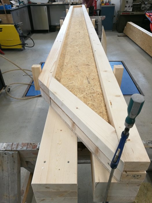
The construction of the beams consists of two 45x70 placed vertically with nail-glued OSB on each side. According to Steiner's theorem, the moment of inertia for the construction is about 17400 cm4, which can be compared to a 45x220 rule that has just under 4000 cm4, in other words, they are quite sturdy beams. In this calculation, I have not considered the extra moment of inertia that the OSB boards may add, so in practice, the difference might be greater, but it's good to have a margin.
The ingredients (for 36 beams) are as follows:
-200m 45x70 C24 (must not be spliced so the length of the wood must be adapted to the construction)
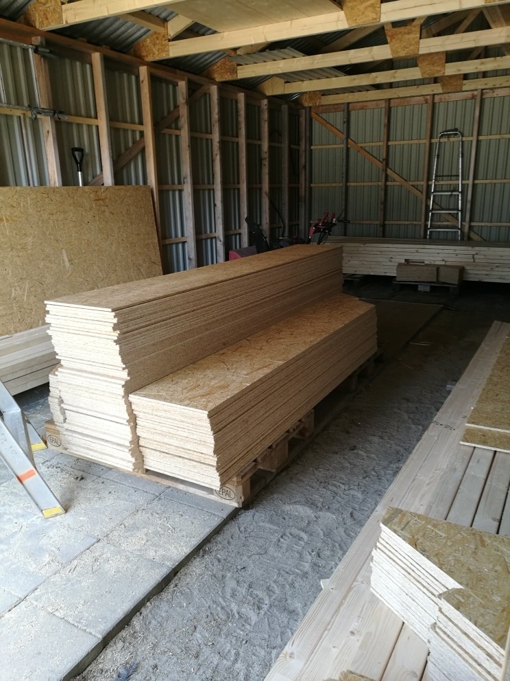
-48 OSB 1197x2500x11 each cut into three equal parts.
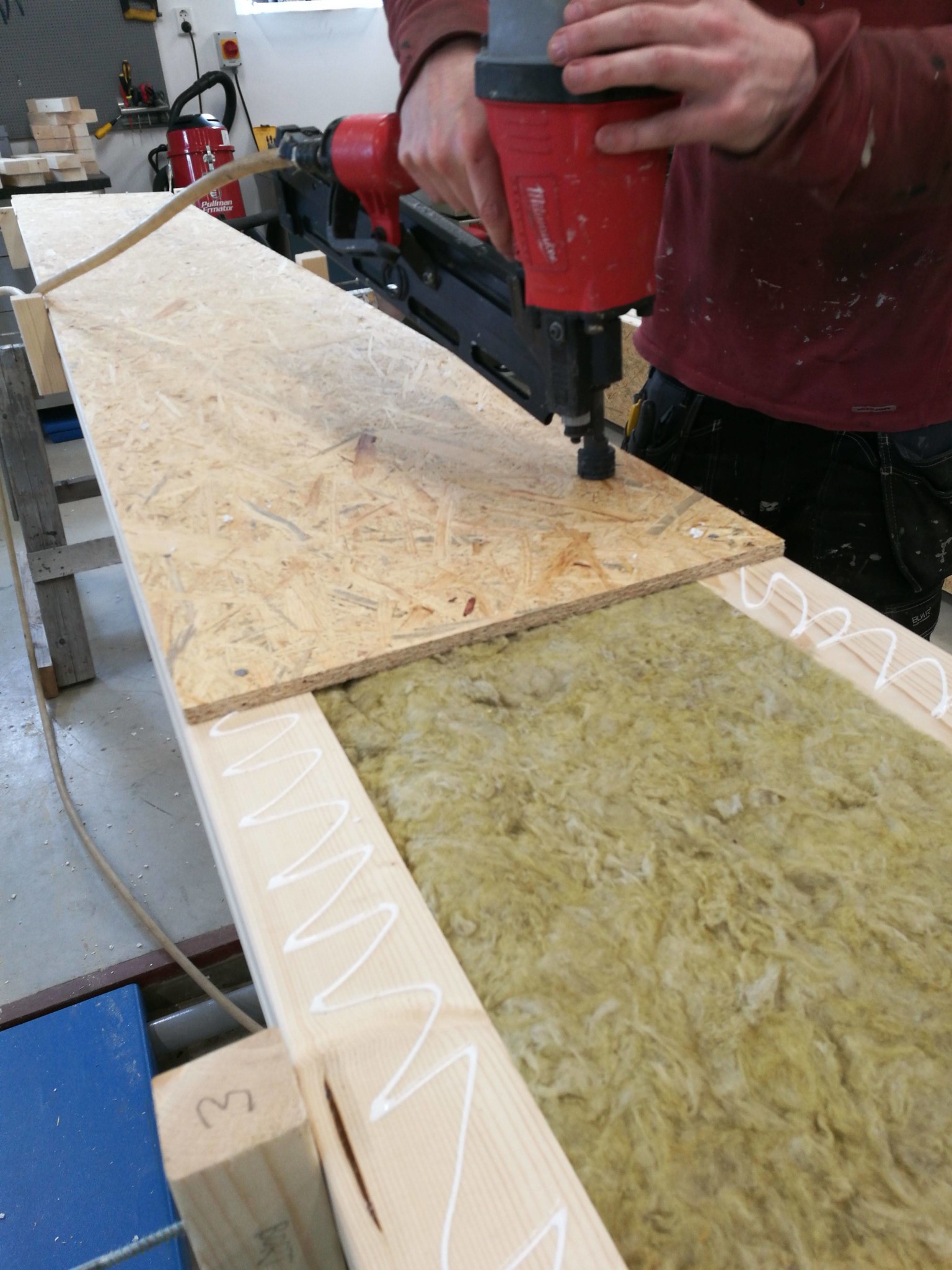
-about 4000 machine nails 2.8x50mm
-about 10l outdoor wood glue/white glue (there are probably many different glues that do the job)
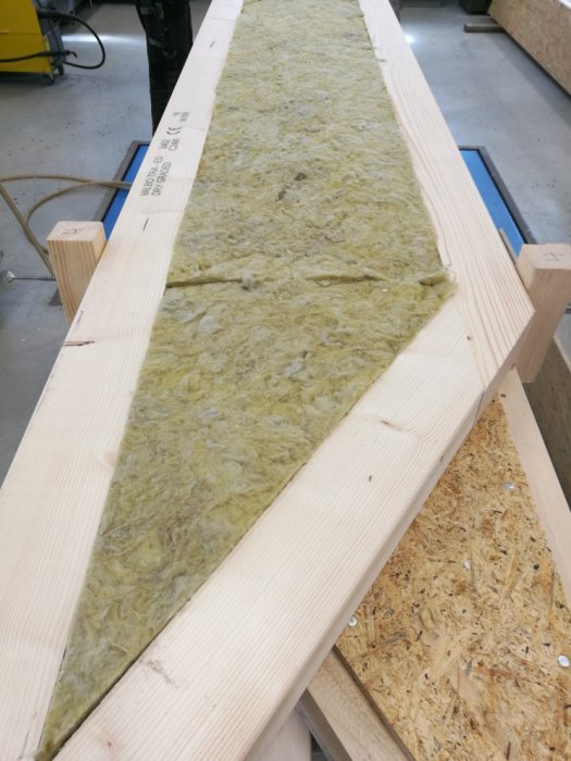
-6 packages 1165x565x45 insulation slabs
Total cost 17070 SEK and about 100 hours of work.
When assembling, it helps a lot to first spend some time building a fixture. It's important to have a completely flat surface, the shape the beams have when the OSB sides are mounted will be retained, hence the importance of a flat surface.
Do not hesitate to come with suggestions and/or questions if you have any thoughts.
I wonder how much money there is to save. I built my house with light beams from massonite beams and it wasn't particularly expensive. One difference is that they only contain 1 sheet of osb in the middle. OSB isn't exactly free nowadays.
I actually don't know. In my case, I could make them customized to my design, which was worth a lot to me. Then I made these when an OSB cost roughly 100 kr for 2.4x1.2m.
SSmurfen1 said:
Can't you build I-joists with 10 mm OSB in the web like Masonite Beams, Hunton, or similar? Could it pay off?
Yes, you can, but it requires more work because you have to mill and glue/press the board onto the studs. With box beams, it's easy to nail the construction together.
NNiq said:
Is it for sound insulation? Or is there another reason?
Primarily for energy efficiency. In my case, the beams are positioned so that the outside of the beam holds outdoor temperature and the inside indoor temperature. Without insulation, the air inside the beam could move freely and create thermal bridges.
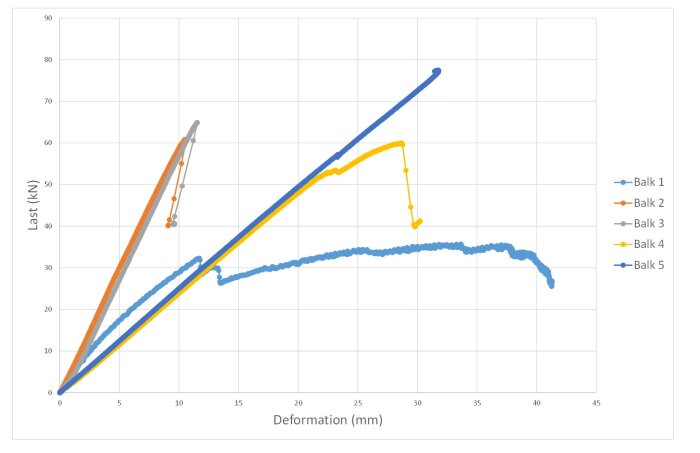
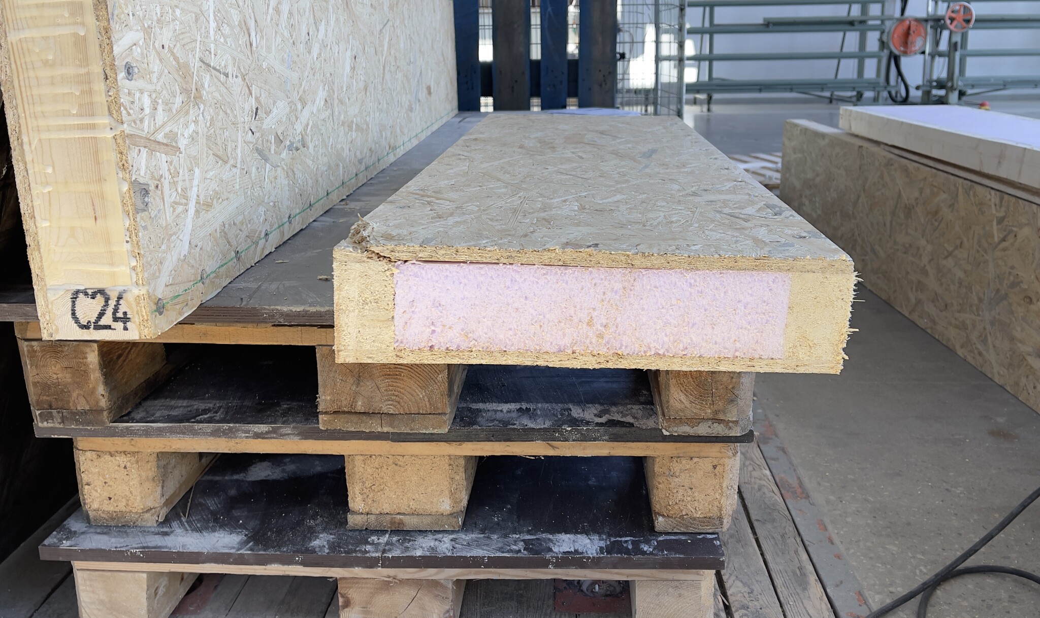
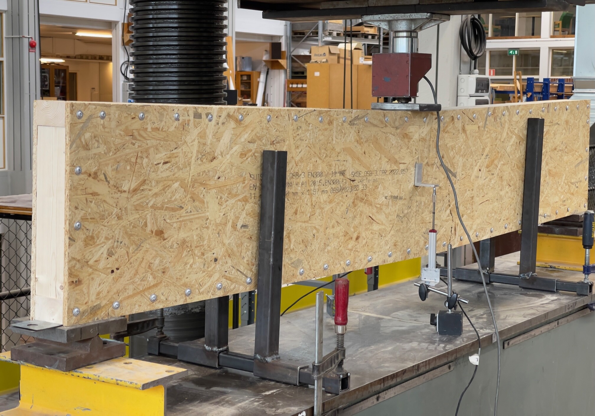
I have made similar beams in the form of box beams. However, they are not optimized at the end supports. I was also considering using regular insulation but switched to XPS after some thought. I tested the beams, a total of five, with both three-point and four-point loading to failure.
Materials, C24 studs 45x95 which were cut to 70 mm, OSB 3 11 mm, XPS 70 mm, PU glue, and construction screws W 6.0x40 were used for beam 1, 3, and 5.
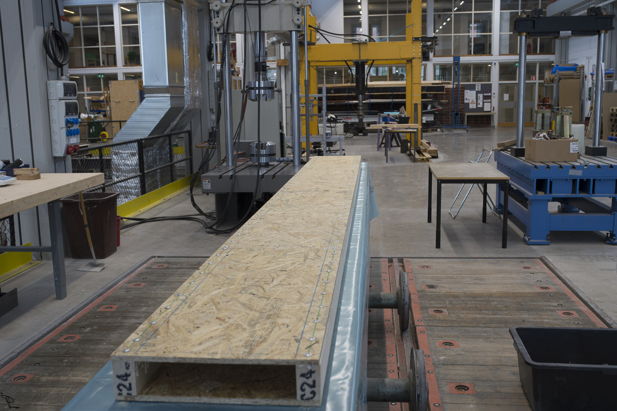
Beams 1 to 3 were 2500 mm, i.e., one OSB long. Beams 4 and 5 were 4200 long. The short beams were load tested with three-point loading and the long ones with four-point loading.
Beam 1 was constructed with only screw connections and a core of XPS.
Beam 2 was both screwed and glued with PU glue. The XPS was also glued to the studs and OSB. Then I removed all screws to simulate only gluing, i.e., the screws were only there to maintain sufficient glue pressure. Certainly, the screw holes theoretically cause a slight weakening, but considering other material parameter variability, it is negligible overall.
Beam 3 was both screwed and glued just like beam 2 but with the difference that the screws were left in.
Beam 4 was the first beam I made and served as somewhat of a pilot project. This beam was also screwed and glued. However, countersunk screws were used.
Beam 5 had the same dimensions as beam 4 but with different screws, see above.
As this is a hobby project, it may take a while before the full report is completed.
Very interesting and nicely presented!
I only have my gut feeling to rely on when it comes to such beams becoming very stable and strong. Your version with glued XPS in the core should become even more stable. I only calculated the theoretical moment of inertia, but I never conducted any load tests.
The question is whether it is cheaper to buy a ready-made light beam with just one board in the middle than to build your own with double boards and XPS. The insulation in the beam hardly adds anything, apart from being needed when building the beam as a box.
Vi vill skicka notiser för ämnen du bevakar och händelser som berör dig.


")