1,955 views ·
0 replies
2k views
0 replies
Drilling through floor joists for stairs in a log house.
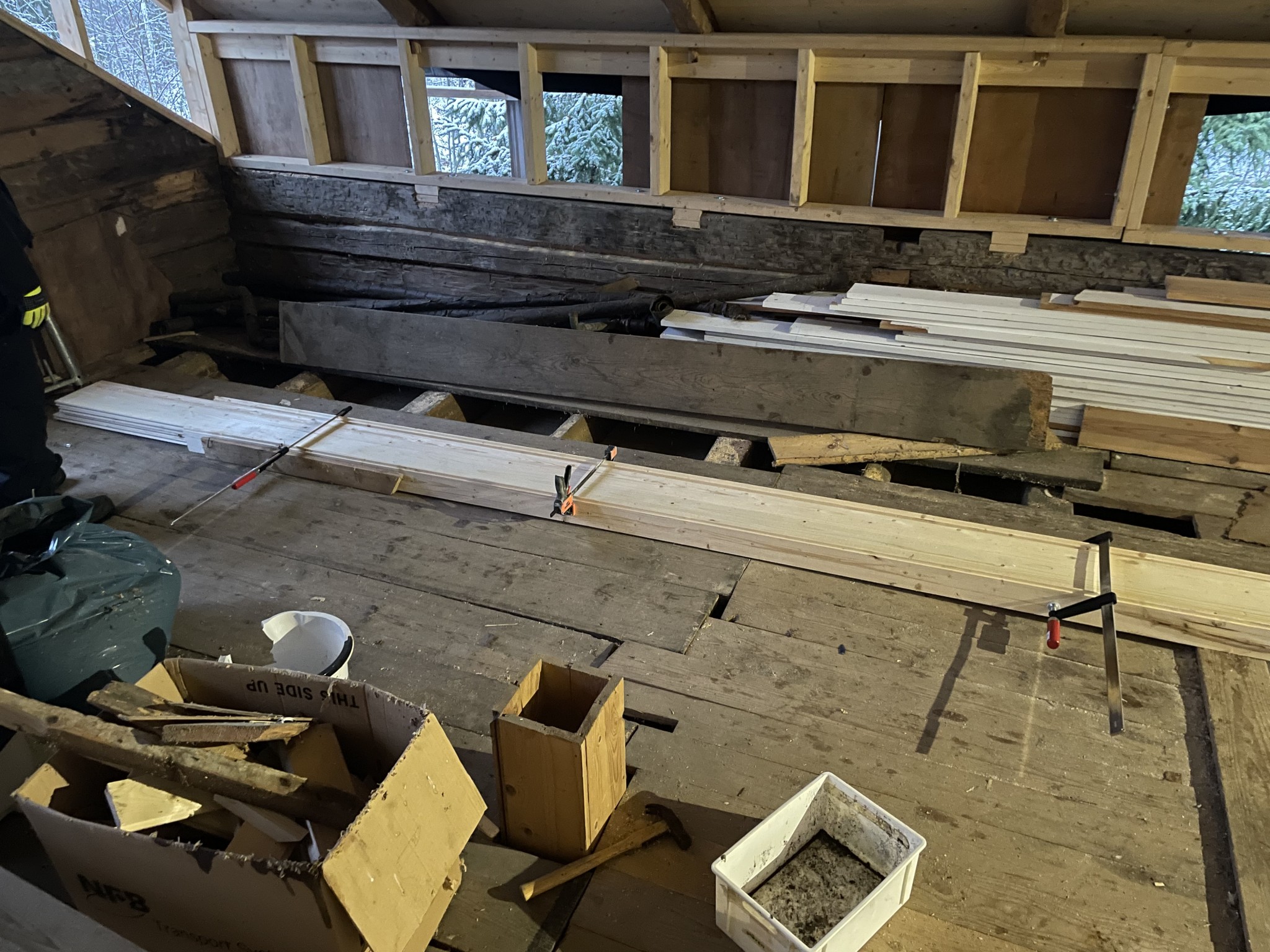
I am sketching a solution for a staircase to the upper floor in an old cottage.
Briefly about the cottage:
Original building, circa 1890: timber frame
Extension, circa 1945, a room with an attached cellar built out from the gable of the house.
All the beams, floors, intermediate floors, and trusses go from the long side to the long side. Span about 4.5 meters between the walls.
Walls in the old part are in standing planks 1-3/4 to 2” thick.
The exterior walls are clad with panel.
The roof has been raised on the upper floor, with a truss wall placed on top of the timber frame/old wall plate and screwed into the timber. The old trusses are reused and mounted with dowels in the new wall plate and angle brackets.
My thoughts:
An L-staircase in the old part of the building, along the external wall that turns along the gable, so you come up facing the center of the room.
For this, I need to cut 5 joists in the intermediate floor and shift the load with a partition wall along the length of the staircase.
What I'm a bit concerned about are potential horizontal loads if the intermediate floor also has the function of keeping the walls upright and preventing them from falling outwards.
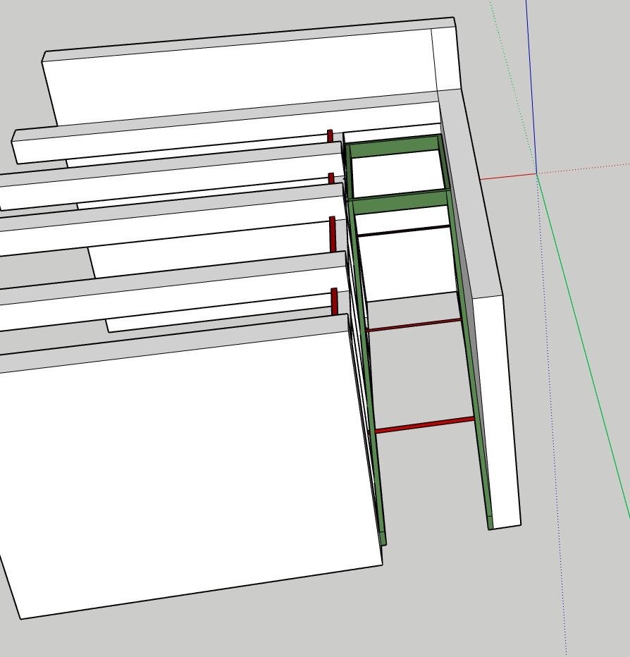
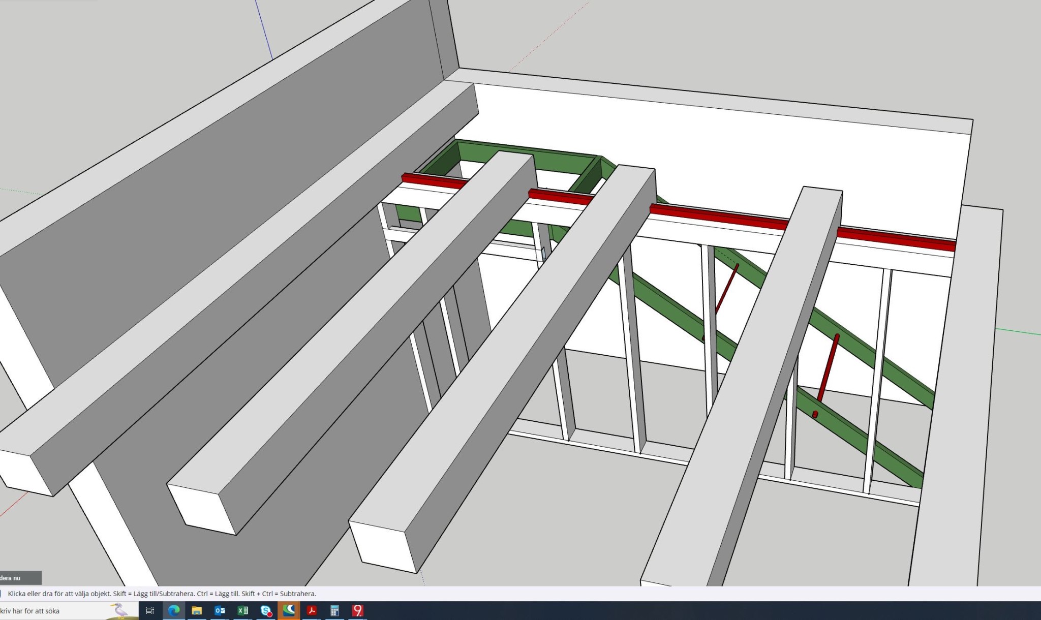
My solution:
Install a partition wall about 1000mm from the exterior wall, so the staircase is built between two walls.
One of the stringers (the stringers are marked in green on the picture) has mounted M16 nuts. The entire stringer is properly screwed into the timber frame.
The other stringer has through holes corresponding to the placement of the nut on the first stringer. This is properly screwed into the stud wall. The stringers are connected with threaded rods/turnbuckles (marked in red on the picture) to be able to handle lateral forces between the load-bearing wall and the exterior wall.
On top of the new wall that is to carry the load of the floor, a horizontal 45x45 batten is mounted (marked in red on the picture). A corresponding 45mm wide and 45mm deep groove is cut out of the beams. The beams are then screwed into the top of the wall.
The beams are connected to each other with noggings, possibly cross-bracing crossed battens to bind them together and also give the construction a little extra stiffness.
My thought is that any loads that would make the wall want to "fall outwards" are absorbed by the beams being hooked into the load-bearing wall, which in turn is connected to the corresponding external wall via stringers and threaded rods.
Am I completely off in my thoughts?
At the moment, I have not been able to come and inspect the attachment of the beams in the wall, so I know very little about it.
Are there any tips on this?
Briefly about the cottage:
Original building, circa 1890: timber frame
Extension, circa 1945, a room with an attached cellar built out from the gable of the house.
All the beams, floors, intermediate floors, and trusses go from the long side to the long side. Span about 4.5 meters between the walls.
Walls in the old part are in standing planks 1-3/4 to 2” thick.
The exterior walls are clad with panel.
The roof has been raised on the upper floor, with a truss wall placed on top of the timber frame/old wall plate and screwed into the timber. The old trusses are reused and mounted with dowels in the new wall plate and angle brackets.
My thoughts:
An L-staircase in the old part of the building, along the external wall that turns along the gable, so you come up facing the center of the room.
For this, I need to cut 5 joists in the intermediate floor and shift the load with a partition wall along the length of the staircase.
What I'm a bit concerned about are potential horizontal loads if the intermediate floor also has the function of keeping the walls upright and preventing them from falling outwards.
My solution:
Install a partition wall about 1000mm from the exterior wall, so the staircase is built between two walls.
One of the stringers (the stringers are marked in green on the picture) has mounted M16 nuts. The entire stringer is properly screwed into the timber frame.
The other stringer has through holes corresponding to the placement of the nut on the first stringer. This is properly screwed into the stud wall. The stringers are connected with threaded rods/turnbuckles (marked in red on the picture) to be able to handle lateral forces between the load-bearing wall and the exterior wall.
On top of the new wall that is to carry the load of the floor, a horizontal 45x45 batten is mounted (marked in red on the picture). A corresponding 45mm wide and 45mm deep groove is cut out of the beams. The beams are then screwed into the top of the wall.
The beams are connected to each other with noggings, possibly cross-bracing crossed battens to bind them together and also give the construction a little extra stiffness.
My thought is that any loads that would make the wall want to "fall outwards" are absorbed by the beams being hooked into the load-bearing wall, which in turn is connected to the corresponding external wall via stringers and threaded rods.
Am I completely off in my thoughts?
At the moment, I have not been able to come and inspect the attachment of the beams in the wall, so I know very little about it.
Are there any tips on this?
Click here to reply
Similar threads
-
How do we reinforce joists for new openings?
Building Physics -
Drilling spots in concrete slabs.
Building Physics -
Drilling concrete slabs - went through two reinforcement rods
Building Materials and Construction Technology -
Hole drilling in joists.
Building Materials and Construction Technology -
Bärighet betongbjälklag vid håltagning
Vatten & Avlopp