Hello,
I am wondering if this load-bearing swap looks correct or incorrect?
If it is incorrect, who can I contact to address it properly?
A bit of background:
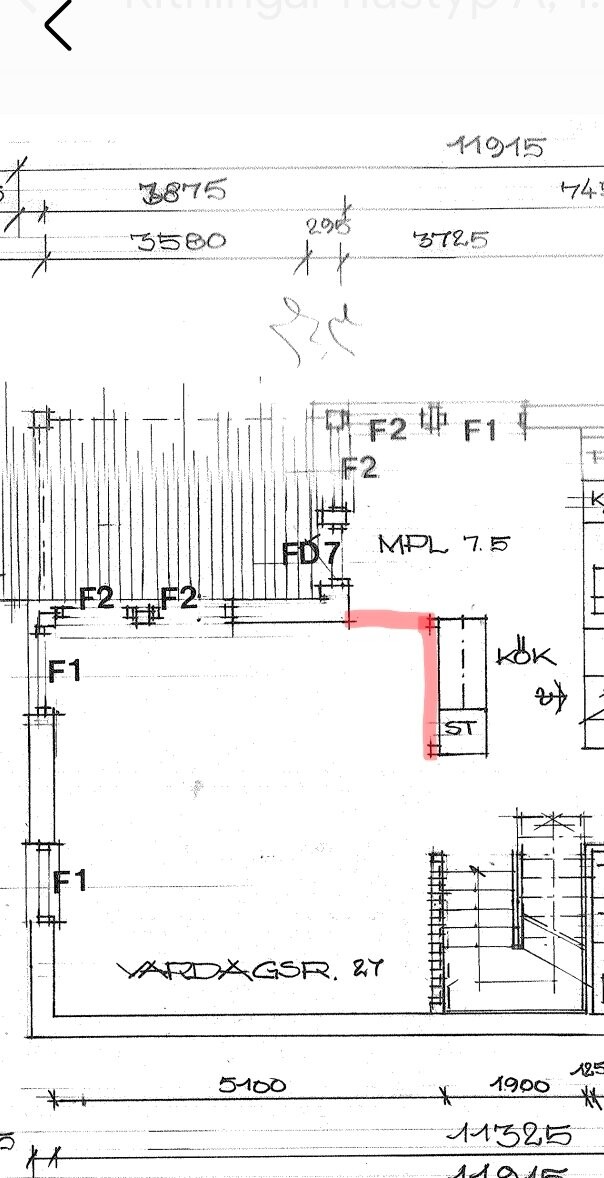
The previous owner removed a wall on the ground floor in the middle of the house (1.5 floors). The wall was shaped like an L.
I find it strange that there is no "pillar" of any kind at the corner where the beams meet. But I am not knowledgeable about construction techniques.
I have contacted the municipality and the previous owner, but it seems no report or calculation of the loads was made.
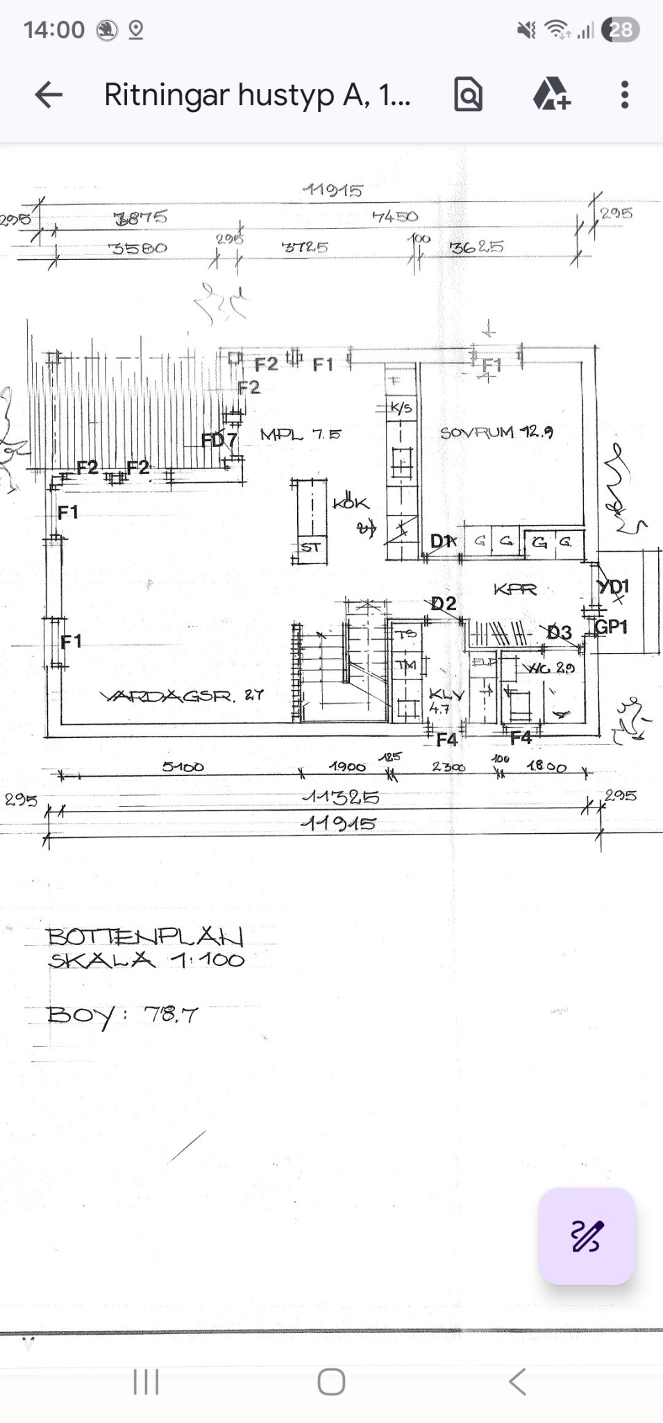
Attaching pictures of the load-bearing swap and a drawing showing what the house looked like originally.
I am wondering if this load-bearing swap looks correct or incorrect?
If it is incorrect, who can I contact to address it properly?
A bit of background:
The previous owner removed a wall on the ground floor in the middle of the house (1.5 floors). The wall was shaped like an L.
I find it strange that there is no "pillar" of any kind at the corner where the beams meet. But I am not knowledgeable about construction techniques.
I have contacted the municipality and the previous owner, but it seems no report or calculation of the loads was made.
Attaching pictures of the load-bearing swap and a drawing showing what the house looked like originally.
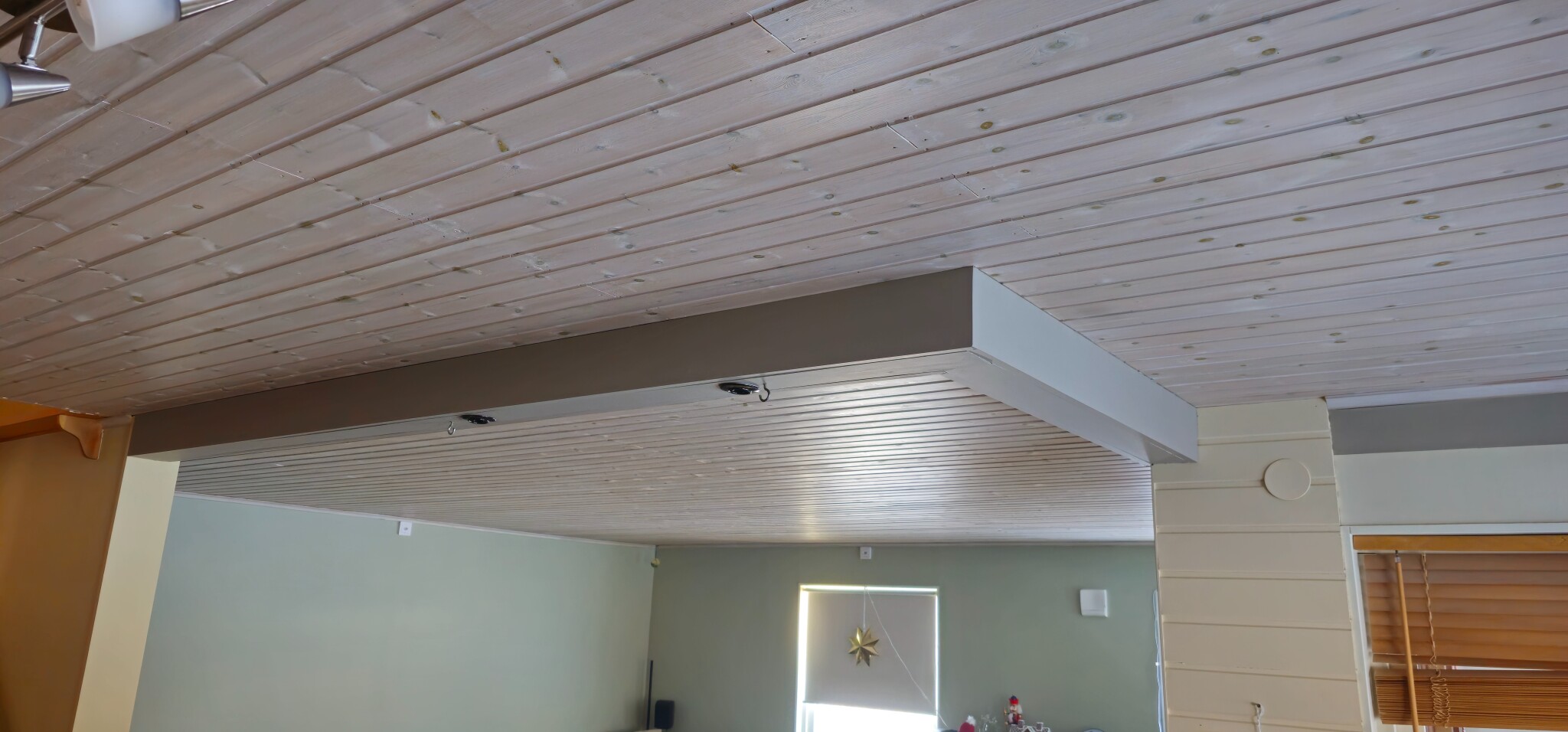
I don't know anything about this, so I apologize for any stupid questions. Do you mean that the beams are just decorative and can basically be removed, or that it's a load-bearing structure that is incorrect?Dr Benz said:
It wouldn't surprise me if it was decorative since there was originally a shelf hanging from the beam with wine glass hangers and lights.
The attic lacked a hatch when I bought the house, so nothing has been done up there.

1.5 story houses where the roof ridge runs left-right in the drawing usually have a load-bearing wall that runs roughly under the roof ridge. In this case, it would be the wall above the KPR or both above and below.L LeoVix said:Hi,
I'm wondering if this beam configuration looks correct or incorrect?
If it's incorrect, who can I contact to fix it the right way?
Some background:
The previous owner removed a wall on the ground floor in the middle of the house (1.5 stories). The wall was in an L shape.
I find it strange that there isn't a "pillar" of some kind at the corner where the beams meet. But I'm not knowledgeable in construction techniques.
I have contacted the municipality and the previous owner, but there seems to have been no report or calculation of the loads.
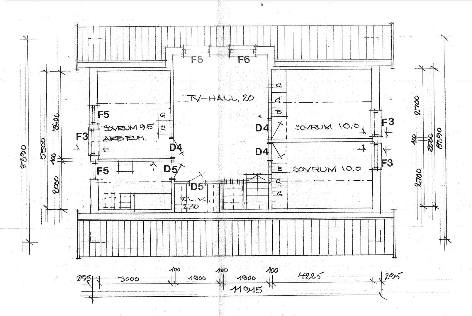
I am attaching pictures of the beam configuration and a drawing showing how the house looked originally.
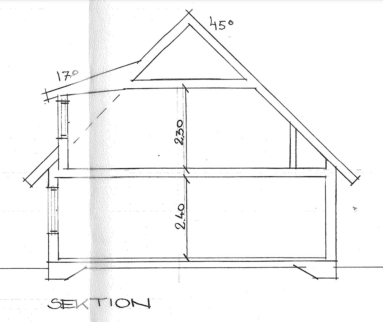
Now, the drawing is very small, but I think it looks like small squares, partly in the corner of the pantry and partly in the corner between the two walls that might have been removed. This might mean that there should be pillars for one or two beams there. You probably need at least a sectional drawing to understand the construction.
Have you checked if the municipality has more drawings?
Have you measured if the ceiling height varies or if the ceiling slopes?
It is structural engineers who work with, for example, load-bearing walls.
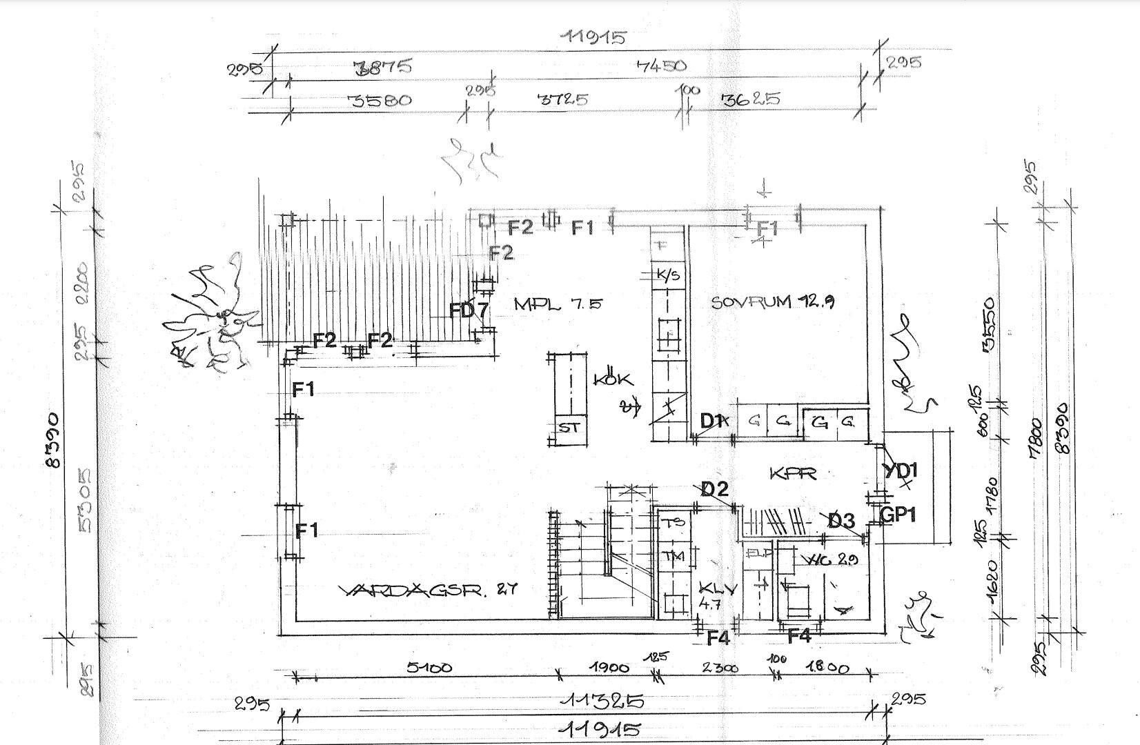
Here are better images of floors 1, 2, and the section. These are the drawings the municipality had besides the facade and plumbing and drainage.BirgitS said:
A 1.5-story house where the roof ridge runs left-right on the drawing usually has a load-bearing wall that runs approximately under the roof ridge. In this case, it would then be the wall above the KPR or both above and below.
Now, the drawing is very small, but I think it looks like there are small squares in the corner of the pantry and in the corner between the two walls that might be removed. This might mean that there should be columns for one or two beams there. You probably need at least a section drawing to understand the construction.
Have you checked if the municipality has more drawings?
Have you measured if the ceiling height varies or if the interior ceiling slopes?
It is structural engineers who work with, for example, load-bearing walls.
A building engineer has measured the ceiling height and slope on one occasion, and there were no deviations beyond what is tolerated.
No silly questions, but I don't understand what function they serve where they are. Since they stick out along the ceiling, I suspect that they are just the top plates from the old wall that someone for some reason didn't remove. (Now that I think about it, they probably couldn't splice the ceiling in a nice way, so they did this instead.)L LeoVix said:I don't know anything about this, so I apologize for any silly questions. Are you saying that the beams are just decorative and can essentially be removed, or that there's an incorrect load-bearing element?
It wouldn't surprise me if it were decorative, as there was originally a shelf hanging from the beam with wine glass holders and lights.
The attic lacked a hatch when I bought the house, so nothing has been done there.
But a look in the attic might provide more info. If it is load-bearing, there should, as you wrote earlier, be a post in the corner.
Someone who knows about constructions needs to determine whether the wall was load-bearing or not. But for that, a construction drawing is required.
No interior wall on the entrance floor is drawn on the section plan, nor is any reinforcement under the slab in the middle, which suggests there are no load-bearing interior walls, but it's probably unusual for an 8 m wide house to have no load-bearing walls.L LeoVix said:
The measurements indicate that what has been removed is not load-bearing.
I'll check with him to see how it is and if I can look at the wall. It's possible he has more documents than the ones I've received from the municipality. Maybe some that show what is load-bearing.Bart said:
It's possible that the splicing could be a reason they kept it. They have spliced the floors as well.No stupid questions, but I don't understand what function they serve as they sit. Since they protrude alongside the ceiling, I suspect they are just the top plates from the old wall that, for some reason, were not removed. (Now that I think about it, they probably couldn't splice the ceiling in a neat way and did it like this instead.)
But a peek at the attic might provide more info. IF it is load-bearing, as you mentioned earlier, there should be a post in the corner.
Someone familiar with constructions will have to determine whether the wall was load-bearing or not. But for that, a construction drawing is required.
Is it common for there to be an existing construction drawing for a house from '78, or does the designer need to start from scratch?
It feels like they might not have included it in the section drawing then. The wall by the stairs, for example, is more solid and consists of pillars and a wooden board. But I don't know if it was like that from the start.No interior wall on the entrance floor is drawn on the section drawing, and there is no reinforcement under the slab in the middle, which suggests that there are no load-bearing interior walls, but it's probably unusual to have an 8 m wide house without any load-bearing wall.
The measurements indicate that what has been removed is not load-bearing.
Based on these drawings, you probably have NO load-bearing wall other than exterior walls, but even a regular interior wall serves a certain function. Does the floor upstairs where it says "TV-HALL" flex?L LeoVix said:
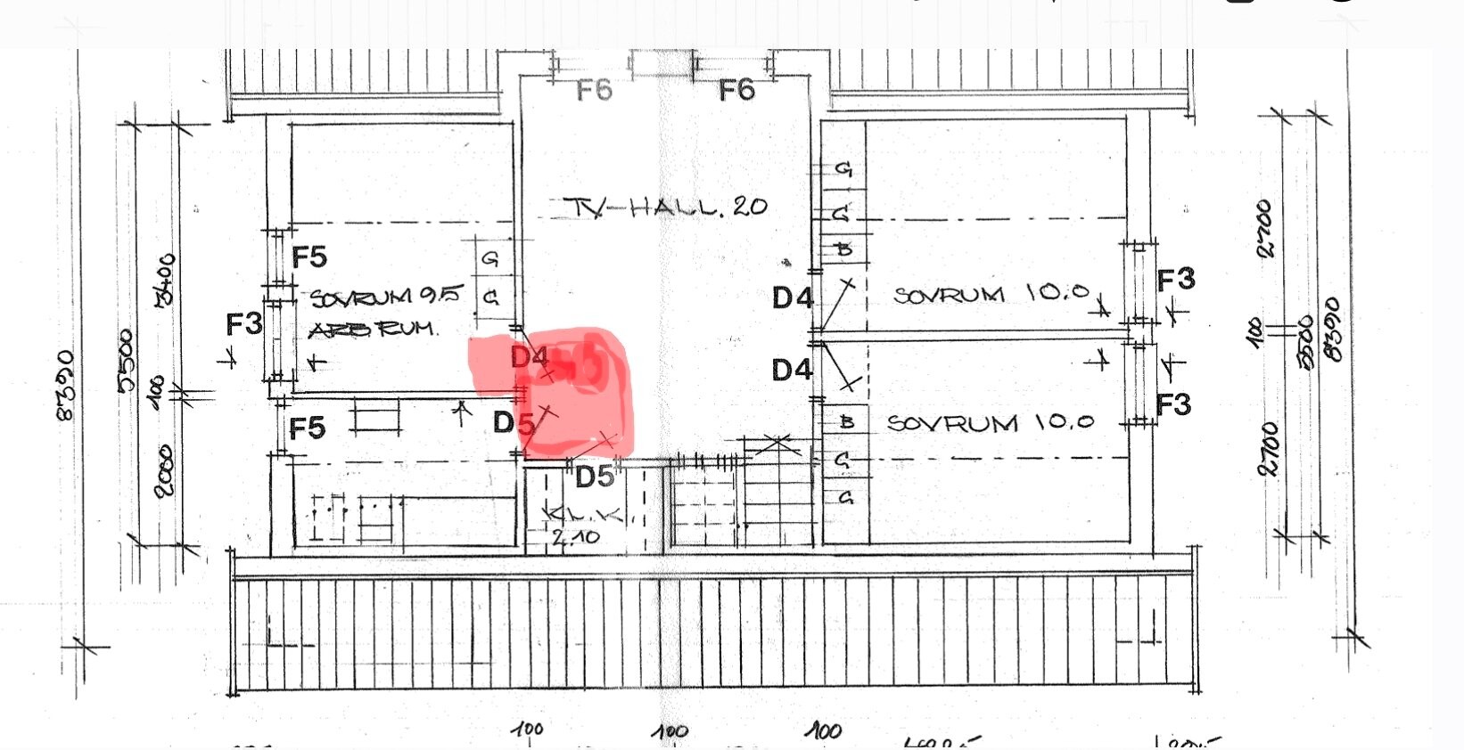
When we moved in, it sloped a lot in the red area on the upper floor. It was a bit like walking downhill into the bathroom.B Boan said:
The carpenter leveled it as best as he could with tretex boards that we laid floor foam and click flooring on. It wasn't as stable as we had hoped, a bit "spongy" and unstable, but better than before.
Click here to reply