Know-It-All
· Västra götaland
· 10 936 posts
Hello everyone!
I have a small problem that I hope someone can help me calculate..
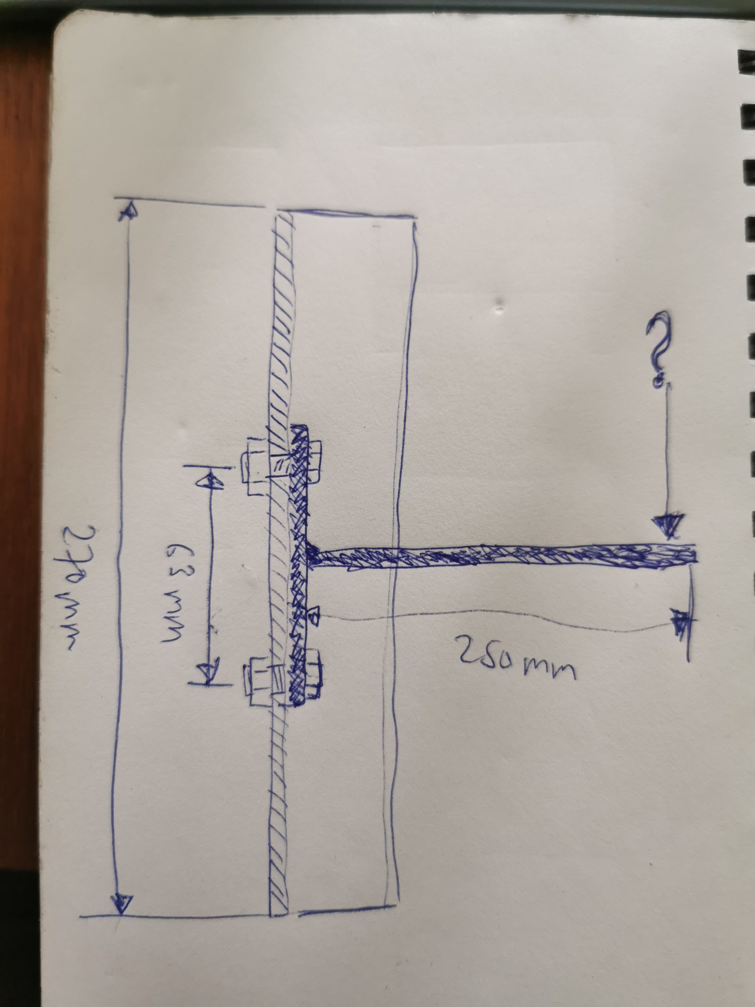
Consider fastening a T to an angle bar made of steel (hot rolled, S235JR) in the dimension 30x30x3, with two 8.8 M6 bolts. The T is unbendable, and the ends of the angle iron are fixed.
What will give way first, the angle iron or the bolts, and at what load does one or the other begin to deform?
I have a small problem that I hope someone can help me calculate..
Consider fastening a T to an angle bar made of steel (hot rolled, S235JR) in the dimension 30x30x3, with two 8.8 M6 bolts. The T is unbendable, and the ends of the angle iron are fixed.
What will give way first, the angle iron or the bolts, and at what load does one or the other begin to deform?
It probably requires a bit more info to be able to answer.
What is the T made of? But with a 250mm overhang, my guess would be that the T will give way before the screw joint. In the link below, you will find the yield and tensile strength for screws.
https://www.google.com/url?sa=t&sou...FjAEegQIAxAB&usg=AOvVaw1ezPWoBB816SBURotOqN50
What is the T made of? But with a 250mm overhang, my guess would be that the T will give way before the screw joint. In the link below, you will find the yield and tensile strength for screws.
https://www.google.com/url?sa=t&sou...FjAEegQIAxAB&usg=AOvVaw1ezPWoBB816SBURotOqN50
Know-It-All
· Västra götaland
· 10 936 posts
Isn't it possible to assume that the T is made of something indestructible/infusible, for simplicity's sake?
The interesting part is whether 30x30x4 angle iron is stronger or weaker than 2xM6... In other words, does it need to be dimensioned up, or can you maybe go down to 25x25x3...
The interesting part is whether 30x30x4 angle iron is stronger or weaker than 2xM6... In other words, does it need to be dimensioned up, or can you maybe go down to 25x25x3...
Do not have access to simulate this at home. Possibly at work next week. What purpose is the construction supposed to serve? Where would you like it to deform first?
I get a feeling that it is for the Locost build. Then I would consider whether it is a vital part or a part that doesn't matter much if it gives way. If it bends at the angle iron, it should cause a smaller reaction than if a screw breaks.
I get a feeling that it is for the Locost build. Then I would consider whether it is a vital part or a part that doesn't matter much if it gives way. If it bends at the angle iron, it should cause a smaller reaction than if a screw breaks.
Know-It-All
· Västra götaland
· 10 936 posts
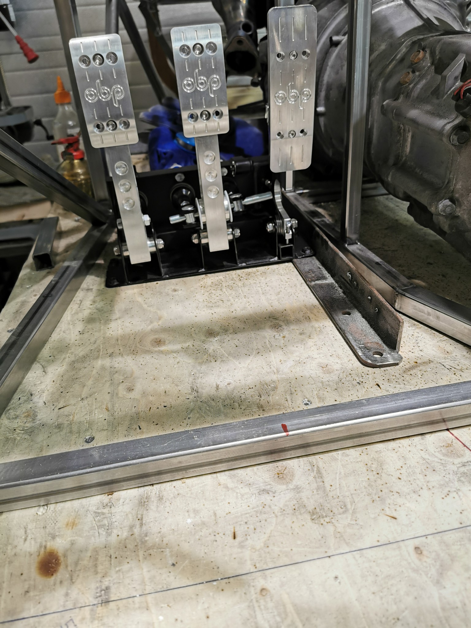
Yes, the T is the pedal box, 63 mm is the distance between the attachment points on it. The idea is to attach it to two pieces of angle iron...A Anderscurl said:I don't have the means to simulate this at home. Possibly at work next week. What purpose is the construction supposed to serve? Where would you like it to deform first? I get the feeling that it's for the Locost build. Then I would consider whether it's a vital part or a part that doesn't matter much if it gives way. If it bends at the angle iron, it should give a smaller reaction than if a screw breaks.
SFRO wants it to withstand 100 kilos of pressure on the brake pedal, and it surely does with 25x25x2 angle iron since the pedal box itself is made of 1.8 mm sheet metal... But I'm thinking of going up a bit just to be safe...
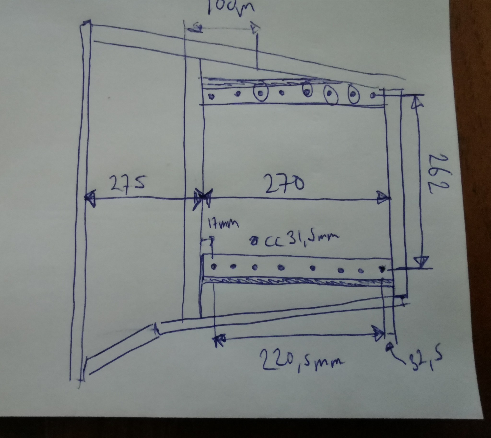
Concept image and drawing from above
Last edited:
If you're mounting on both sides as you’ve drawn, it's probably perfectly fine to handle 100kg force on the brake pedal without flex. Even with 25x25x2mm. As you say, the pedal box is in thinner sheet metal. The frame angle irons will be attached to is probably 25x25x2mm square tube, I assume.
Know-It-All
· Västra götaland
· 10 936 posts
Yep, 25x25x2 at the back and front...A Anderscurl said:
The question is if one should go with 25x25x3 angle iron, the advantage would be that it becomes the same height as the square tubes...
The small increase in weight is probably worth taking to get both a more stable and uniform mount. That weight also lowers the center of gravity. Take the opportunity to think about something to rest your left foot on during longer drives. Some mini shelf or knob or something. It can be tedious in the long run not having anywhere to put it.
Click here to reply