Hello,
We are planning an attefall extension and it will include a construction drawing.
I used some Linux programs like LibreCAD and FreeCAD and made a first sketch. But it ended up with me exporting to jpg format and adjusting some lines in Paint in Windows.
I just wanted to hear if you see anything noteworthy in this draft.
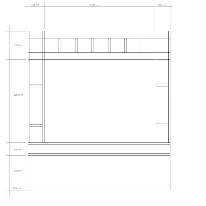
The base is a concrete slab, 100 mm.
Then bricked Leca in 750 mm.
The wood will be 45 * 175 in the construction.
In the floor 45 * 225.
I don't think the scale turned out quite right, which might be due to my lack of knowledge about the Linux programs I mentioned.
If you see anything that suggests it simply isn't good enough, feel free to comment.
I guess it should be a section? The drawing is not "professionally done." All components should be presented, i.e., dimensions of the timber, insulation, waterproofing, roof pitch, fastenings etc.
I don't want to be rude, but I can't quite piece it together. An alternative program is Sketchup, which is available on the web. And you can draw by hand. But the municipality wants it to be "professionally done."
Hi,
We are planning an attefall extension and it will include a construction drawing.
I used some Linux programs like librecad and freecad to make an initial sketch. But in the end, I had to export to jpg format and adjust some lines in Paint in Windows.
Just wanted to hear if you see anything that stands out or needs attention in this draft.
The foundation is a concrete slab, 100 mm.
Then masonry Leca in 750 mm.
The wood will be 45 * 175 in the construction.
In the floor 45 * 225.
I don't think the scale turned out completely alright, which may be due to my lack of knowledge about the Linux programs I mentioned.
If you see anything that suggests it's simply not good enough, feel free to comment.
Best regards,
Fredrik
[image]
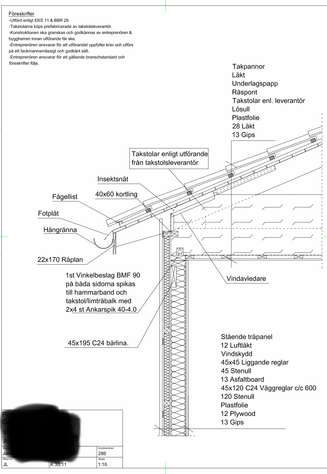
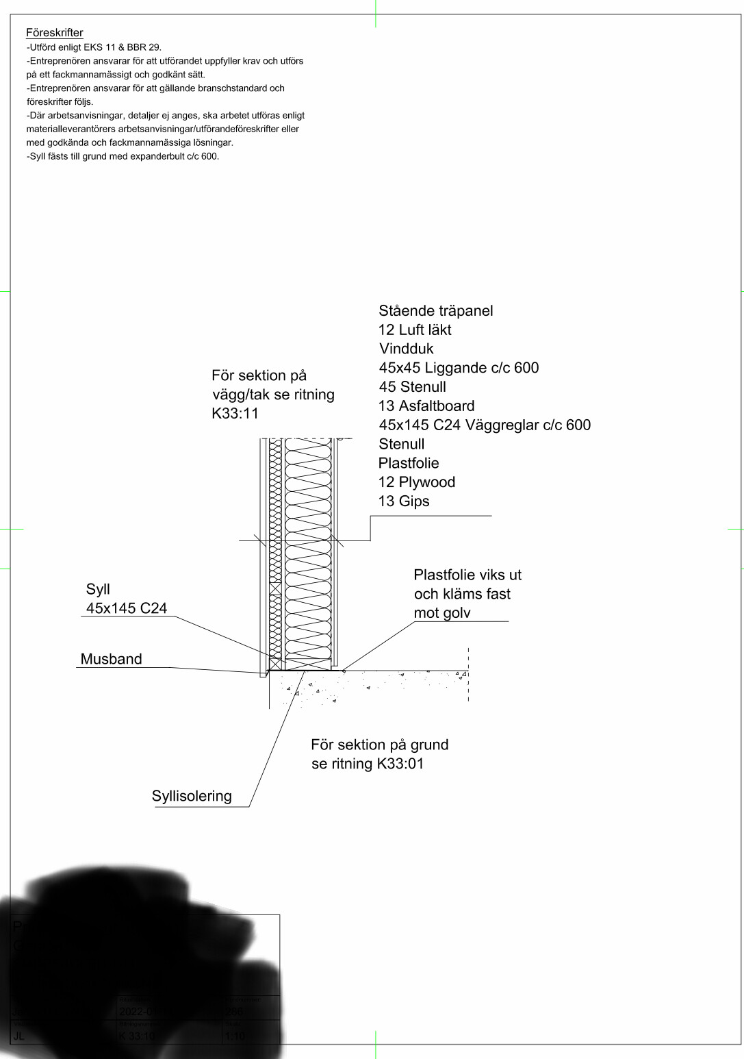
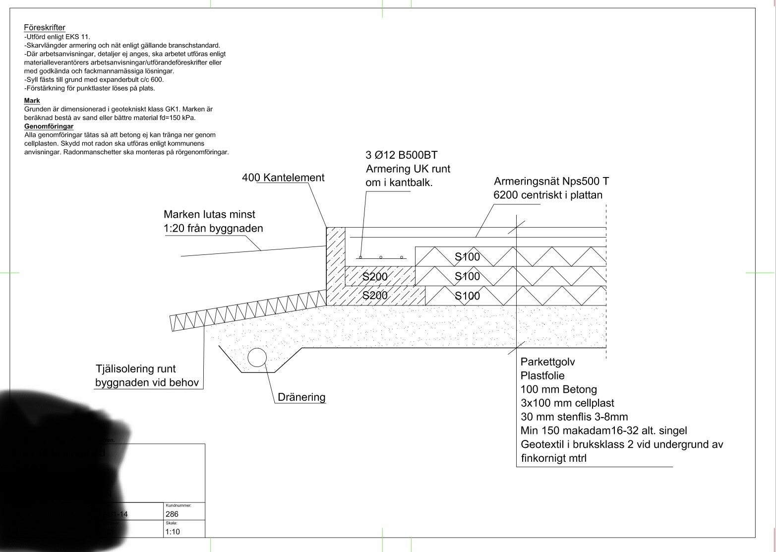
Here you have some K-drawings of a wooden wall on a concrete slab that you can take inspiration from..