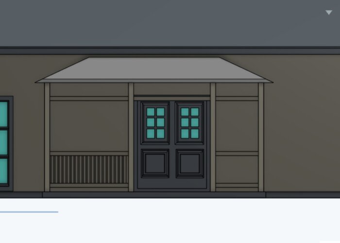
I am currently designing a veranda with a hipped roof and have a few questions. Questions are marked in red.
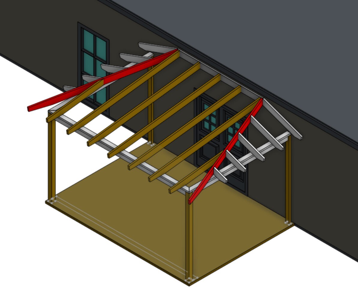
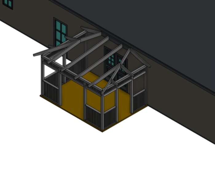
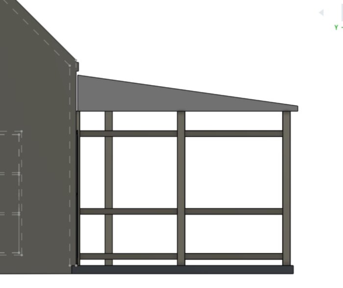
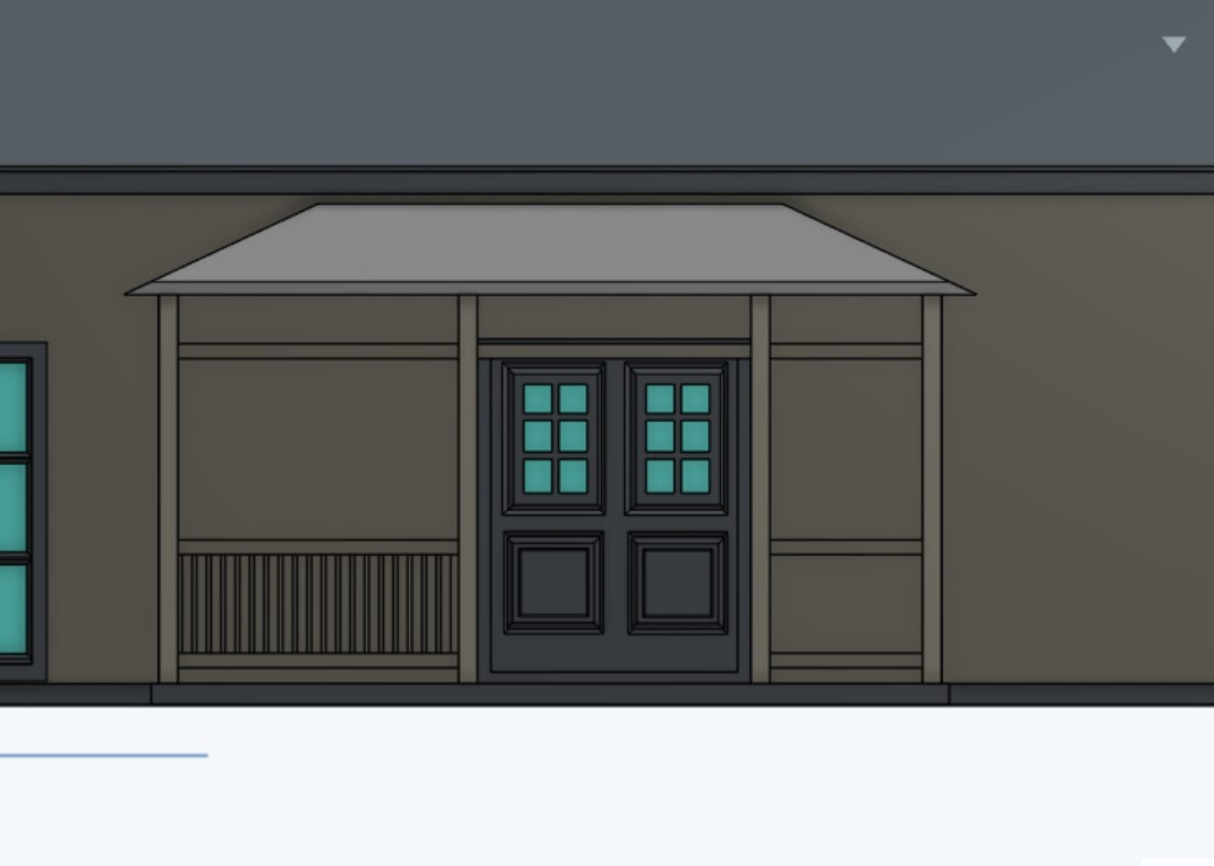
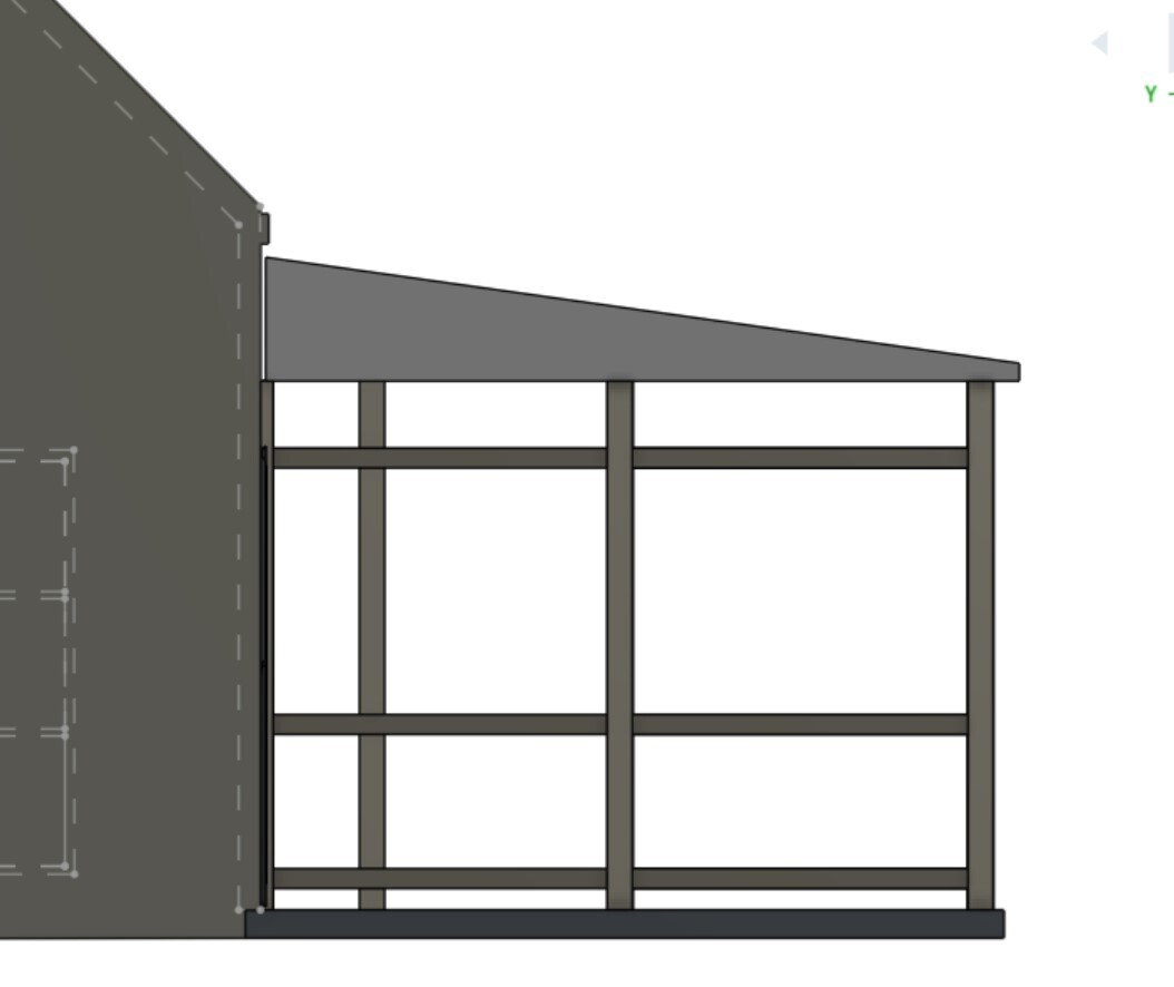
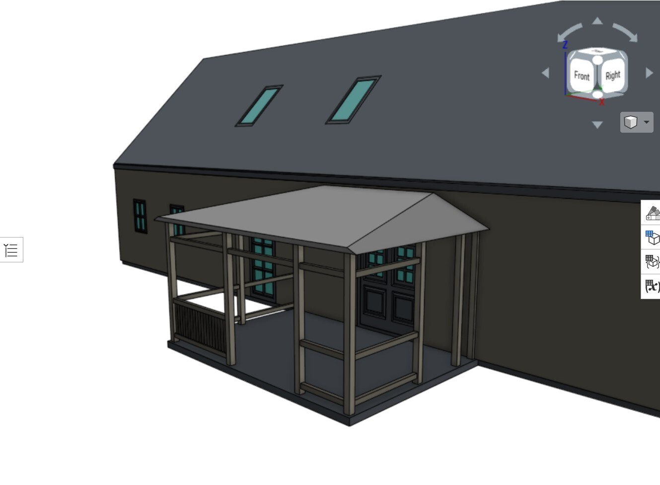
I've made a quick 3D model draft to have something concrete to look at. Below you can see three pictures of it.
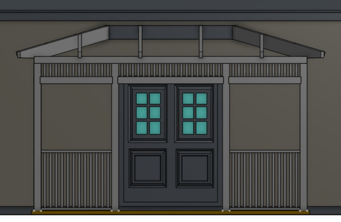
The model is far from being completed and the dimensions aren't quite accurate. My wife and I have made some revisions that haven't been updated in the model yet. The differences are that the veranda should be centered in front of the door. The reason it isn't in the model above is because we tried to keep it under the 15 m2 allowed without a building permit, so we moved the veranda to the left so that the intended seating area wouldn't be impacted by the active door leaf in the double doors. After seeing how it turned out in the model, we have now decided that we will make it larger to be able to center it in front of the double doors. In the pictures, there is barely any roof overhang either. This was also to play with the idea of maximizing the usable space under the roof which, in reality, would probably result in a fairly dull appearance. We will also abandon this since we will exceed 15m2 anyway. The exit on the short side seen in the last picture will also be centered on the short side. The railing is also not finished in the pictures.
The intended veranda will be 5.2m (outer dimensions) wide as this is the largest we can accommodate without interfering with a downspout on the left side. The depth is intended to be 3.5m (outer dimensions). I envision a roof overhang of about 300mm beyond the bearer all around. Is 300mm beyond the bearer a reasonable roof overhang?
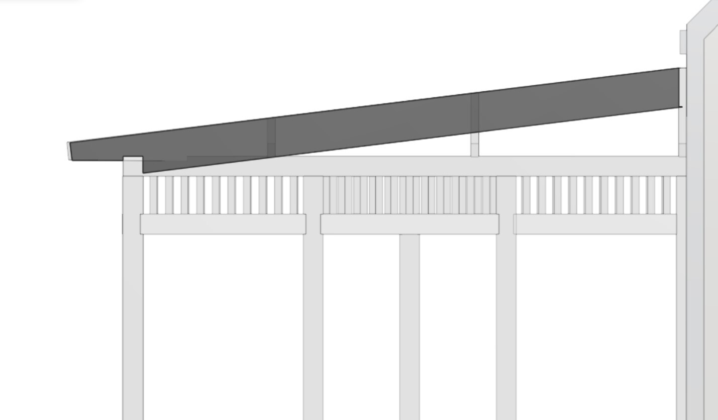
The angle of the roof in the model is 8 degrees. I'm considering lowering it to 7 degrees to save about 60mm in height. Is 7 degrees a good angle for a standing seam metal roof?
In the pictures, the roof is approximately 60mm below the existing gutter which extends about 150mm from the façade. Is it a sensible solution to let the metal roofing connect up behind the gutter? Could there be issues with water splashing up against the vented soffit?
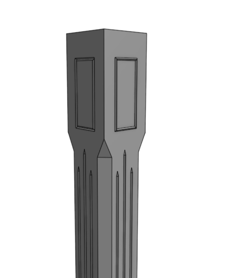
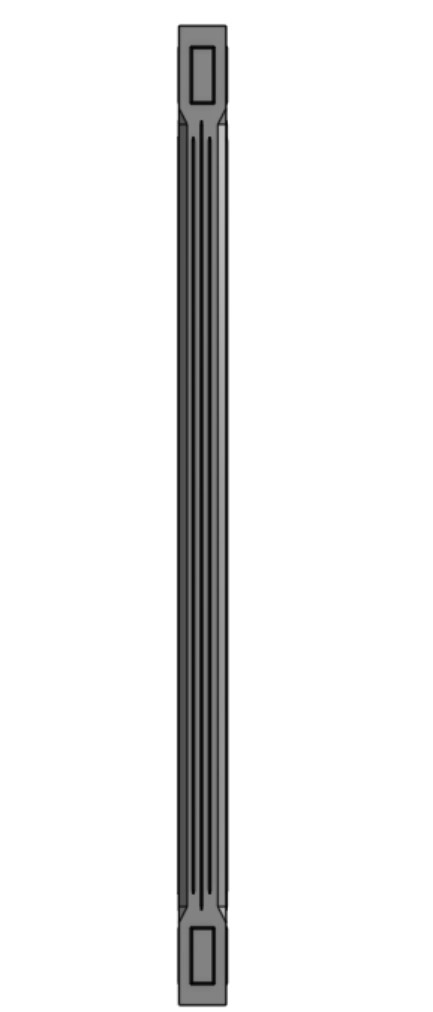
Regarding the load-bearing structure, I am considering using either pre-milled 130x130 posts or buying 115x115mm laminated timber posts and milling them myself. See the picture below
I made the above model to familiarize myself with the program I'm sketching in and accidentally showed it to my wife, so now I have to follow through and start milling.
The idea is to use split posts, that is, 115x57.5 next to the façade and then a post in each corner, two at the entrance which will be placed 1600mm apart inside/inside, one on each side of the small entrance on the short side, and one in the middle of the closed short side. The maximum distance between posts will then be 1715mm C/C at the entrance and approximately 1500mm towards the corner posts. This should be fully sufficient in terms of the posts' load-bearing capacity?
When it comes to the bearer itself, I'm a bit unsure about what the best solution is. I'm considering recessing a beam centrally into the posts and fastening the whole thing with ET-T screws (Pondus screws), but I'm not entirely sure if one needs to supplement with a wall plate/top plate on top to align with the "roof trusses." Is a wall plate/top plate necessary? Pros/Cons? What dimension is recommended for the bearer?
Then we come to the roof trusses themselves. Here, I'm very uncertain about what dimension to choose. My plan is to have a visible structure, so I want it to look nice. The span isn't too large; between the inner bearer and the outer, it's about 3.2m, slightly longer on the diagonal beams. What dimension is sensible here? We live in central Skåne, so snow loads aren't massive.
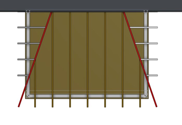
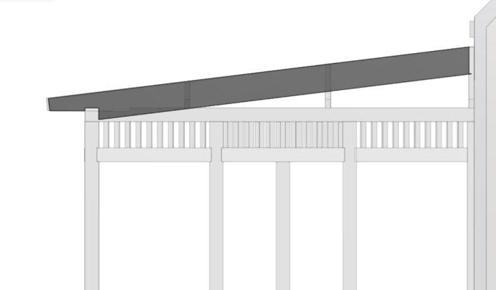
As you can see in the pictures, I want a longer flat section in the middle as it suits my house better. The angles on the hip roof fall at 25 degrees in the above pictures. I understand this entails some headache with the diagonal beams because they need to be moved further out over the walls on the short sides to achieve the same roof overhang all around. Are there any other pitfalls here?
My plan is to make a "sharp" model based on feedback here where each beam should be drawn in so that I can build from the top down. I want to get an idea of the opening I can achieve between the floor, which in this case will consist of wooden decking, and the upper bearer. The goal is to keep the height of the load-bearing structure as low as possible so that I can have slats even above the entrances in a uniform style.
Thank you very much for taking the time to read my long thread start and an even bigger thank you for all the feedback I can get here.
300 mm eaves seem reasonable considering the size of the roof
7 degrees work, it's often said that you shouldn't have less than 1:10 in slope, which is barely 6 degrees. If you want an even flatter roof, you must have full lengths of the roof sheets
I would extend the roof sheeting to the facade and up under the existing facade covering. It seems unlikely that you'll get splashes inside the gutter.
The posts will be strong enough
Probably no wall plate needed since you don't have any forces pushing the bearer outward
Without being a structural engineer or having calculated it, I would go with 45x170 or possibly 45x195 for the roof rafters. We have 45x170 on our upper rafters for our pergola with a span of 3400 and they barely flex when I hang from a single rafter
See no pitfalls but aesthetically I would try to get the break in the corner and not indented as you have drawn it - but that's a matter of taste.
Thank you very much for the response.
I'm considering possibly reducing the dimension of the beam and adding a hammarband anyway since I will need to prop up the slanted rafters a bit so that they align with the rafters going straight. A rule placed on top of the beam then provides a little more opportunity to conceal the propping in the form of a wedge or similar.
I will definitely make sure to have the break centered over the outer corner. The reason the image looks strange with an extra angle at the front is that I've added a thickness of 100mm to the roof to start calculating the construction height with the beam. The program reacted a bit strangely to that and the bevels turned out a bit odd.
Can a beam consisting of 145x45 with a lying 45x90/45x120 work here, or will that be too weak? The lower, the better, of course, but it needs to hold.
You have such a short distance between the posts that I think it works with 45x145 and a horizontal 45 on top of that, just make sure to screw them together so they cooperate.
We only have a pergola so there is no roof to hold snow, so we have a fairly wide gap between them and the idea when I chose 170 mm joists is to put channel plastic or glass in the future, so we have 800 mm c/c.
OK.
I will attempt to start drawing a more detailed model this week. I will probably aim for c/c 600-800, choosing whichever fits evenly with the slanted studs.
It will likely become a separate thread later on once the construction really gets underway.
I will return to the thread during the week with new pictures.
There we go.
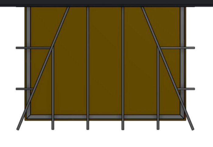
A first draft of the rule framework. 653.75mm cc between the roof trusses. 600mm cc on the short sides. Now it's spinning a bit too much in the CAD-brain for an amateur so it's time to take a break for the evening.
After pondering the results of yesterday's drawing, a few more questions have arisen. As it is drawn today, I have about 2300mm free from the underside of the beam to the intended floor level. I have already changed from an 8 to a 7-degree angle on the roof. I can't raise the roof further without making the sheet metal work under the gutter impossible, and the floor can't be lowered much more. The floor itself will consist of a wooden deck to be built on what is currently a gravel-paved yard. I will likely cast channels and fix them up with NTR-class A 120mm joists resting on the concrete channels.
Since I would like to have some form of trellis/slats above the entrances and maintain an opening height of 2100mm, I would like to raise the beam further.
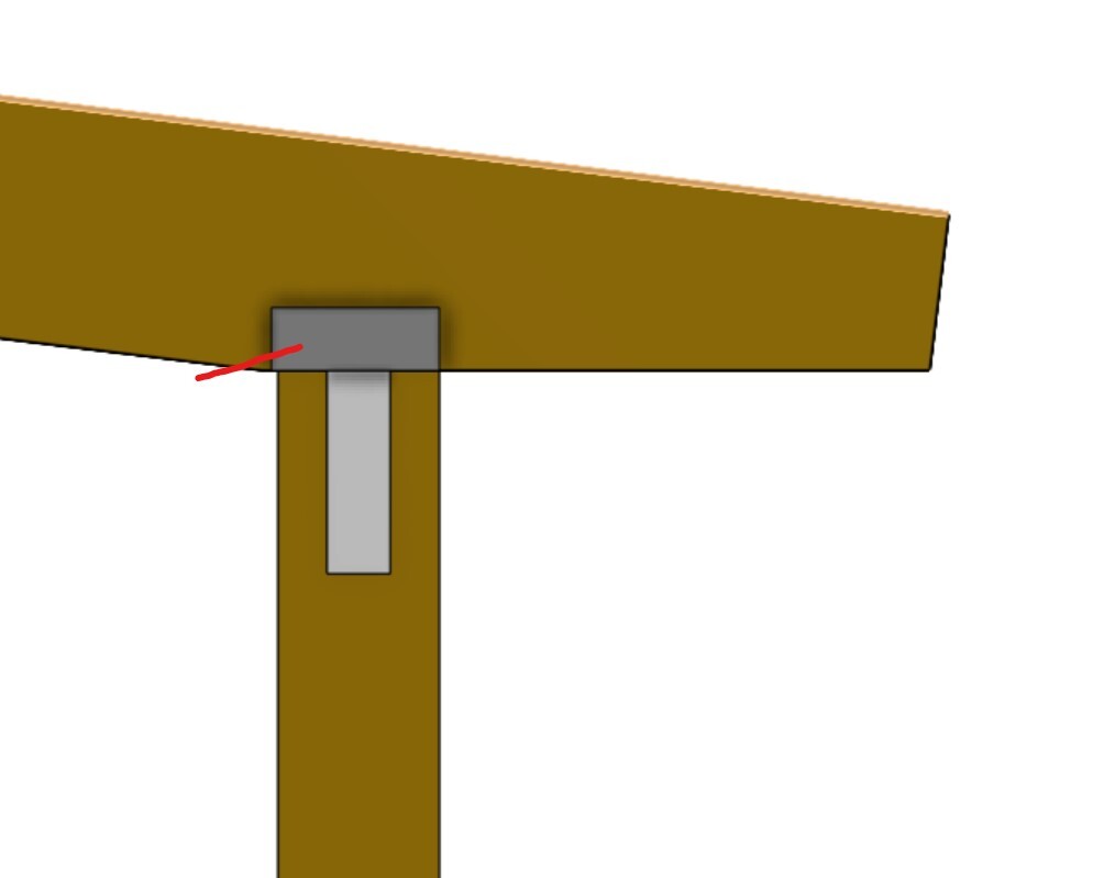
As it is drawn today, I have let the joists fall towards the beam and then cut them parallel to the top of the beam.
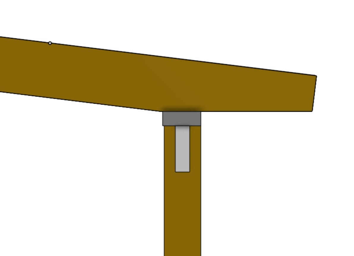
In the image above, I have raised the beam by 45mm, which means it needs to be notched into the joists. The red line is meant to indicate an additional fastening in the form of ET-T/Pondus. Is this solution OK regarding load-bearing capacity? I think the floor joists can be attached with 2 ET-T at each end, so there shouldn't be any problems. Could the beam be raised even higher without encountering any issues?
Can the 145mm joist and the overlying 120x45 be replaced with two 120x45 placed parallel to each other to save height provided they are fastened together with screws? Alternatively, a glulam post similar to those I plan to use as posts? These would then be 115x115mm.
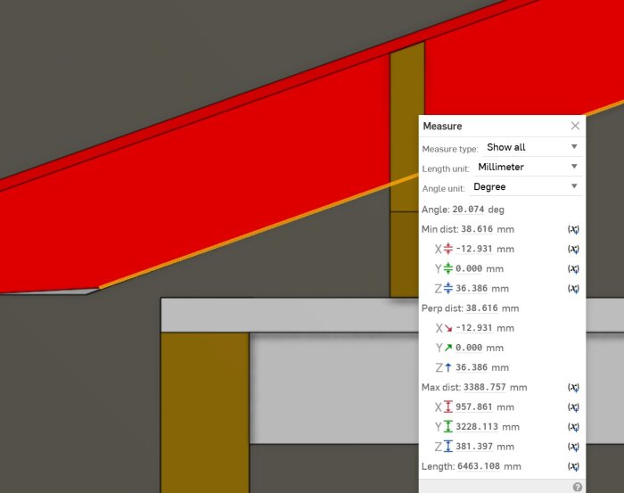
Due to the fact that the angled joist has a different slope than the straight joists, a gap of 36mm is formed between the outermost edge of the beam and the part of the joist directly above it. It might be sensible here to push the beams on the short sides upwards. Another alternative could be moving up to a 195mm joist to then fit it with a wedge.
Seen from directly above, you can see that the outer corner of the tongue and groove will follow the outer corner of the beam since the "nose" of the angled joists lands at a 45-degree angle to the corner of the beam.
I am not entirely 100% sure that this will be the final transition, and I am considering moving the transition inward slightly. Possibly having it start half a rafter further in. This is to get the joist itself more centered over the outer corner. Not because I think it will be something noticeable when everything is completed, but rather because it feels better for some reason.
As usual, I am very grateful for all thoughts and ideas.
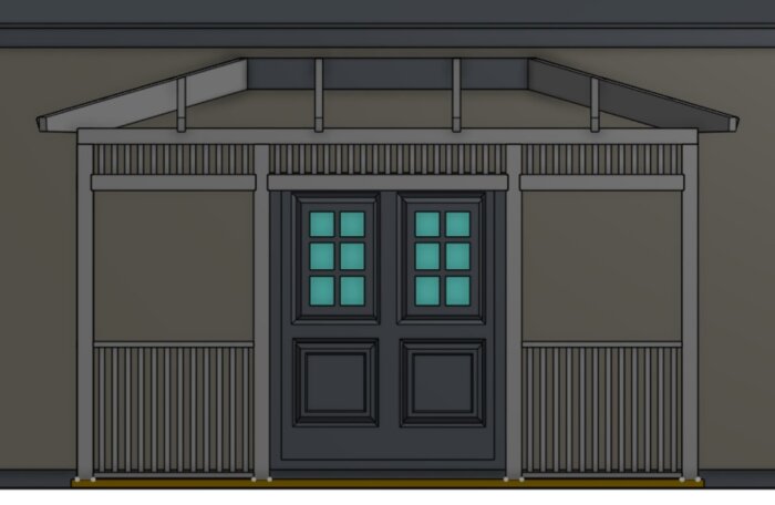
I have now completely revised my drawings.
In the drawings below, I have chosen to size up the roof trusses to glulam 56x225 and then spaced the roof trusses so that they have a maximum distance of 1200mm. The shorter roof trusses on the sides are intended to be standard 45x225 beams due to the limited span.
I have also reduced the flat part of the roof to get nicer angles on the construction.
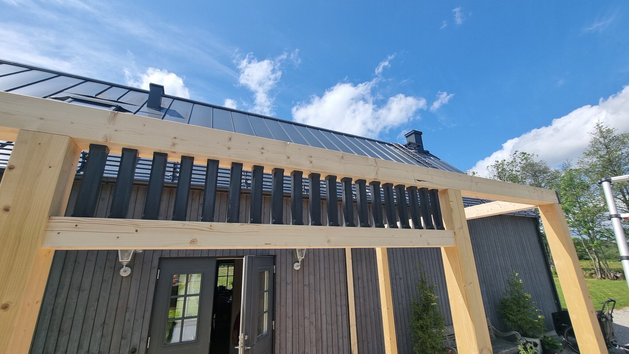
I had some thoughts about trying to raise the load-bearing beam as high as possible to make room for embellishments in the form of slats but decided instead to integrate the slats into the load-bearing beam itself. In the image below, a 115x115 glulam pillar is placed on top of the standing glulam pillars, which also measure 115x115mm. These are mitred in the corners. The lower part of the load-bearing beam also consists of a 115x115 glulam pillar which I intend to rout into the standing pillars, about 15mm deep, and join with crosswise inserted ET-T. Between the two load-bearing beams, there are 40x40 dimension-planed posts with a CC distance of between 90-95mm depending on how long the sections are.
To keep the building height down, I thought of hooking the roof trusses to the load-bearing beam at the front. The longer inclined beams will only need to be hooked about 20mm due to the lower slope required for the noses of the beams to align. The short beams on the sides can be mitred parallel to the ground line without needing additional hooking.
This thread is starting to resemble a blog more than anything else, but I would gladly welcome feedback on my construction.
Nice!
It turned out to be a substantial change in the construction. It will be very strong with those dimensions, maybe a bit overkill, but at least you won't have the roof falling on your head if it snows. 👍😁
Thank you.
The choice of the beams is based on pictures that my wife found of a similar porch, so they are primarily made for aesthetic reasons. If I could have gotten away with 195x45 instead of laminated beams in the rafters, I would have been happy. The cost quickly adds up with laminated beams, not to mention the consequences of a mistake when cutting the angles. I can't exactly drive to the local lumberyard and pick up a new beam for a couple of hundred.
Then the building permit was approved, and construction has begun.
Started by building the frame of the deck with a floating construction. What is not visible in the pictures is that I removed the slabs at the outer corners to then dig a hole about 30cm deep in the bedding layer under the corners. Here, with force and strong conviction, I drove down four 12mm rebar at approximately 45-degree angles at the bottom of the hole to act like tree roots. In the hole, I then cast concrete up to a beam shoe that I fixed in the already leveled frame. The idea here is to anchor against wind loads.
I've been quite bad at taking pictures during the construction time, but here are a few from today.
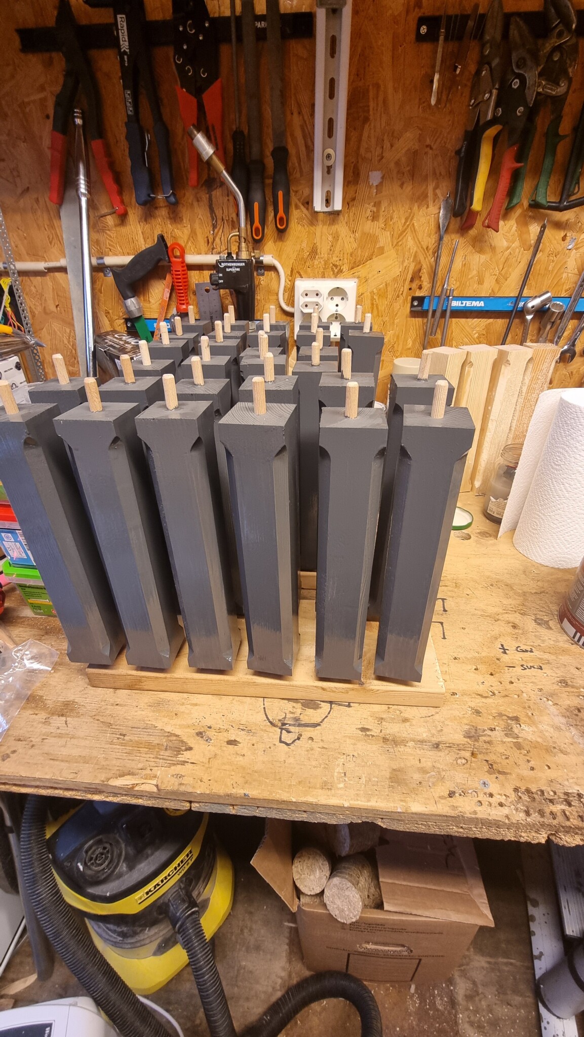
The posts are in place. All end grain is painted before assembly with tjäralin linseed oil paint.
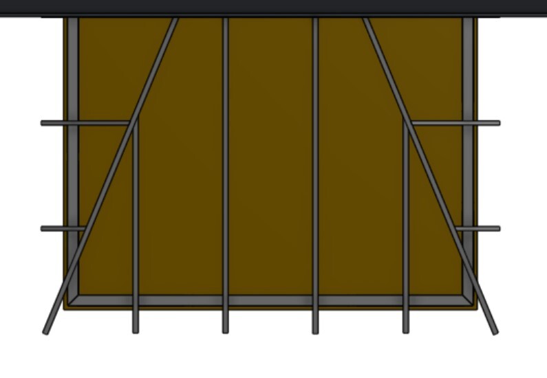
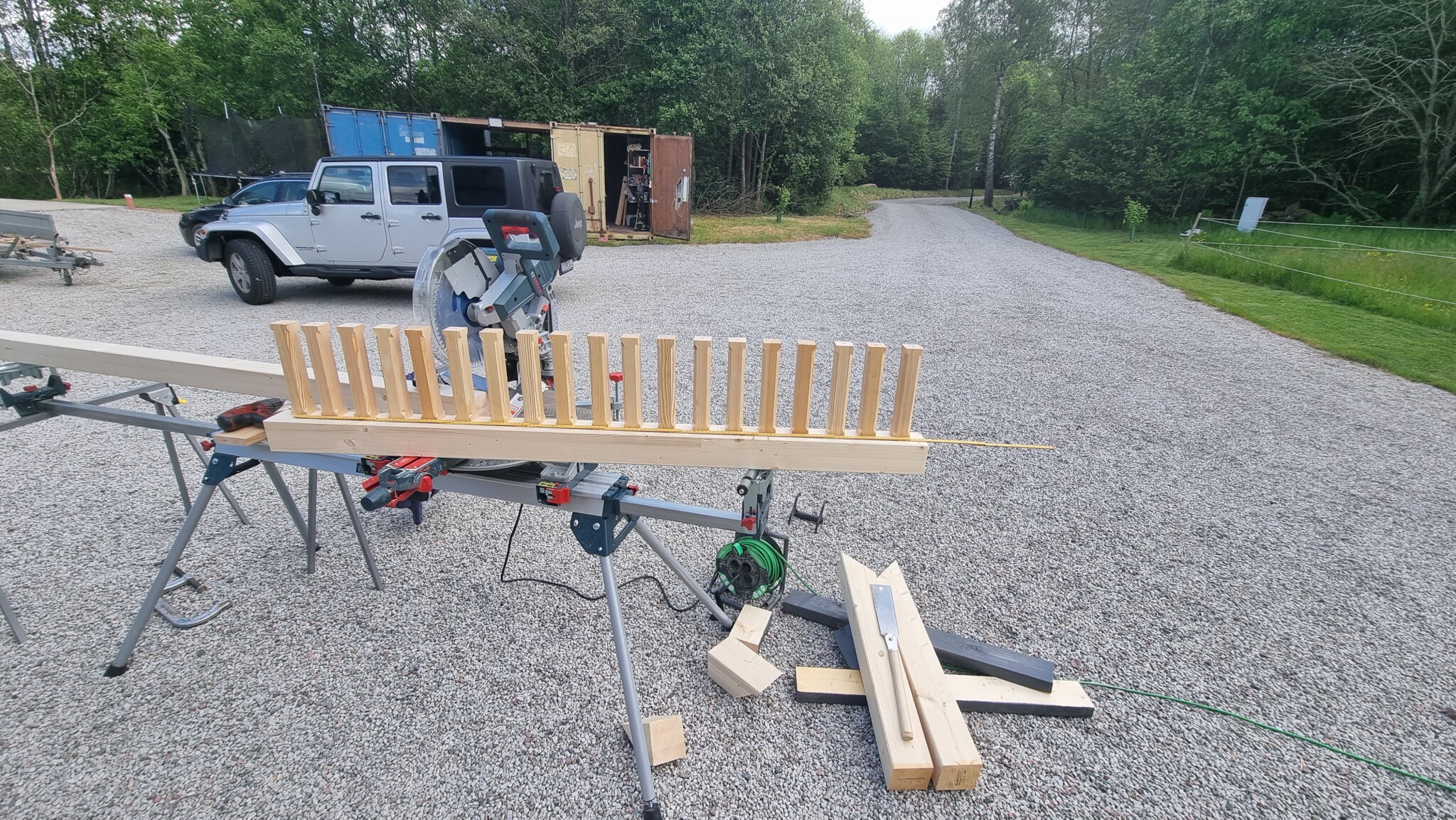
There's been quite a bit of prefabrication during rainy days. I milled and pre-drilled 118 "posts" that will serve as decoration in the bearer. These are 245mm long and made from 43x43mm dimension-planed timber. Had to build a milling jig to be able to mass-produce these. Also bought a drill template from Amazon to get all holes straight at the ends. The posts are mounted with 8mm wooden dowels and wood glue between the upper and lower beam, so the tolerances on the hole pattern are quite tight.
In one of the pictures, you can see a test arrangement of posts before drilling to get a suitable mutual dimension.
More pictures and updates will come gradually.
I must once again praise Onshape, the world's best tool for drawing in 3D. Insanely generous free version that can generate really good building permit documents in just a few minutes, not to mention all the features of being able to take measurements directly on your mobile as you build.


")