I would need some input regarding a load-bearing wall that is somewhat in the way of my new floor plan. In short, I want to install a laminated beam that has as little depth as possible (which everyone wants, really), and where the width isn't very significant.
The opening will be quite large, 4m, so the beam should be quite substantial. 315mm is probably the maximum we can accept since we can only fit it 45mm into the ceiling...
I've looked at different options for beams but I don't really know how they compare in terms of strength.
I guess my question really comes down to comparing these sizes:
90x315
115x315
140x225
I could also have double 90x225 or 270, anything to reduce the height...
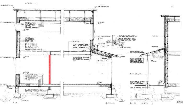
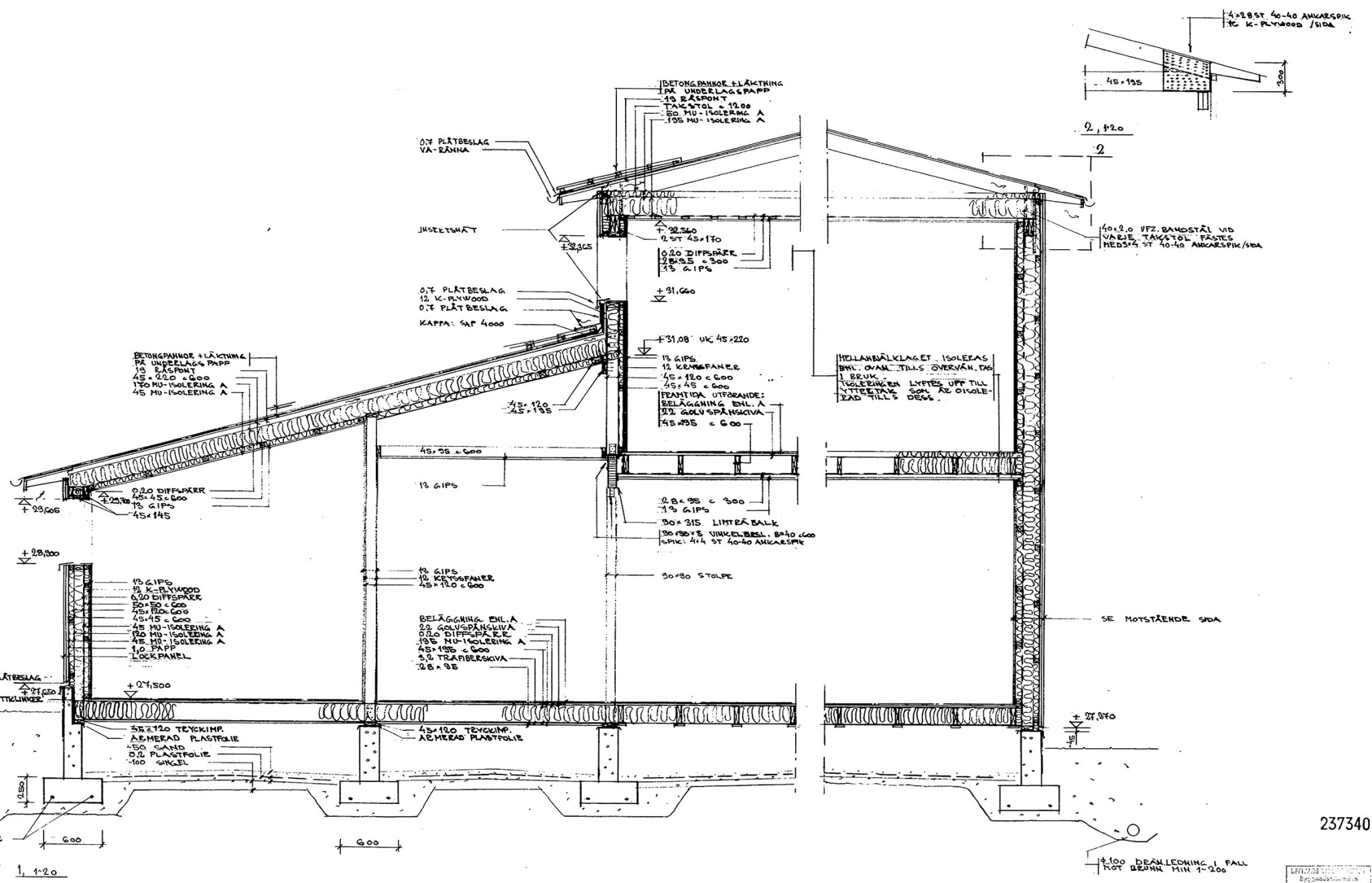
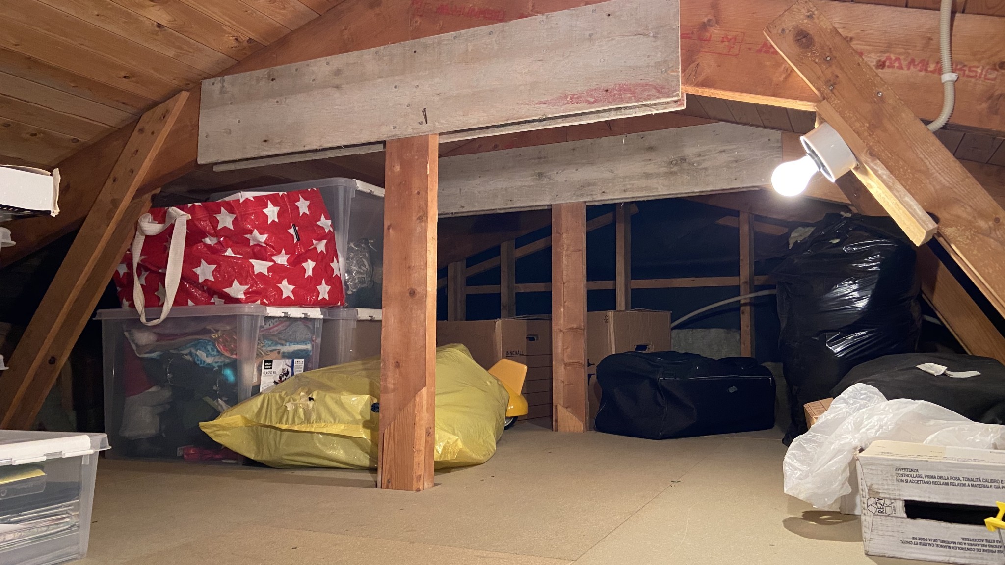
I don’t have very good blueprints to consult, so I have contacted the municipality to see what they have in the archives. I've removed part of the ceiling to see what's behind it and can conclude that the load-bearing wall at least supports the upper floor's floor. There are 45x200 joists resting on the load-bearing wall and supporting the upper floor...
Wooden house with two floors and an attic built in the 1980s in the Stockholm area.
Regardless of the size of the beam required (which assumes proper drawings if calculations are to be made), something can be said about the three glulam dimensions you have specified: 90x315, 115x315, and 140x225. The 115x315 is the stiffest, and the 140x225 is significantly less stiff than the others. With a 4 m span, that one can probably be excluded. The lowest beam that can replace 90x315 and 115x315 is 215x270. It is even slightly better. It's worth knowing that you can always reduce the height of a glulam beam by increasing its thickness. However, this always comes with the cost of greater material usage. A 4 m long 215x315 can handle about 15 kN/m in distributed load without bending down more than 1/300 of the span. On a primary beam of this type, there may be reasons to limit the deflection further.
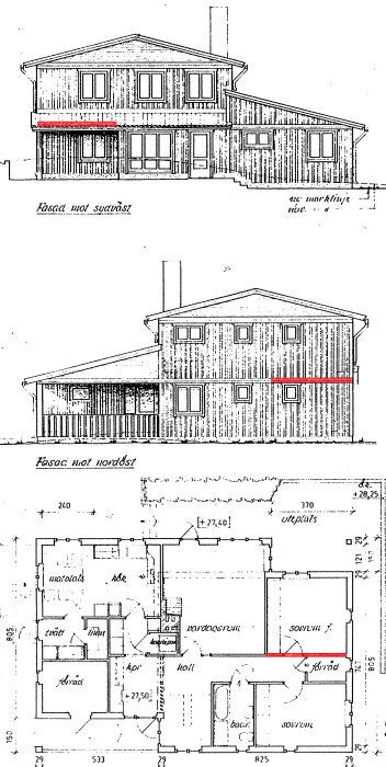
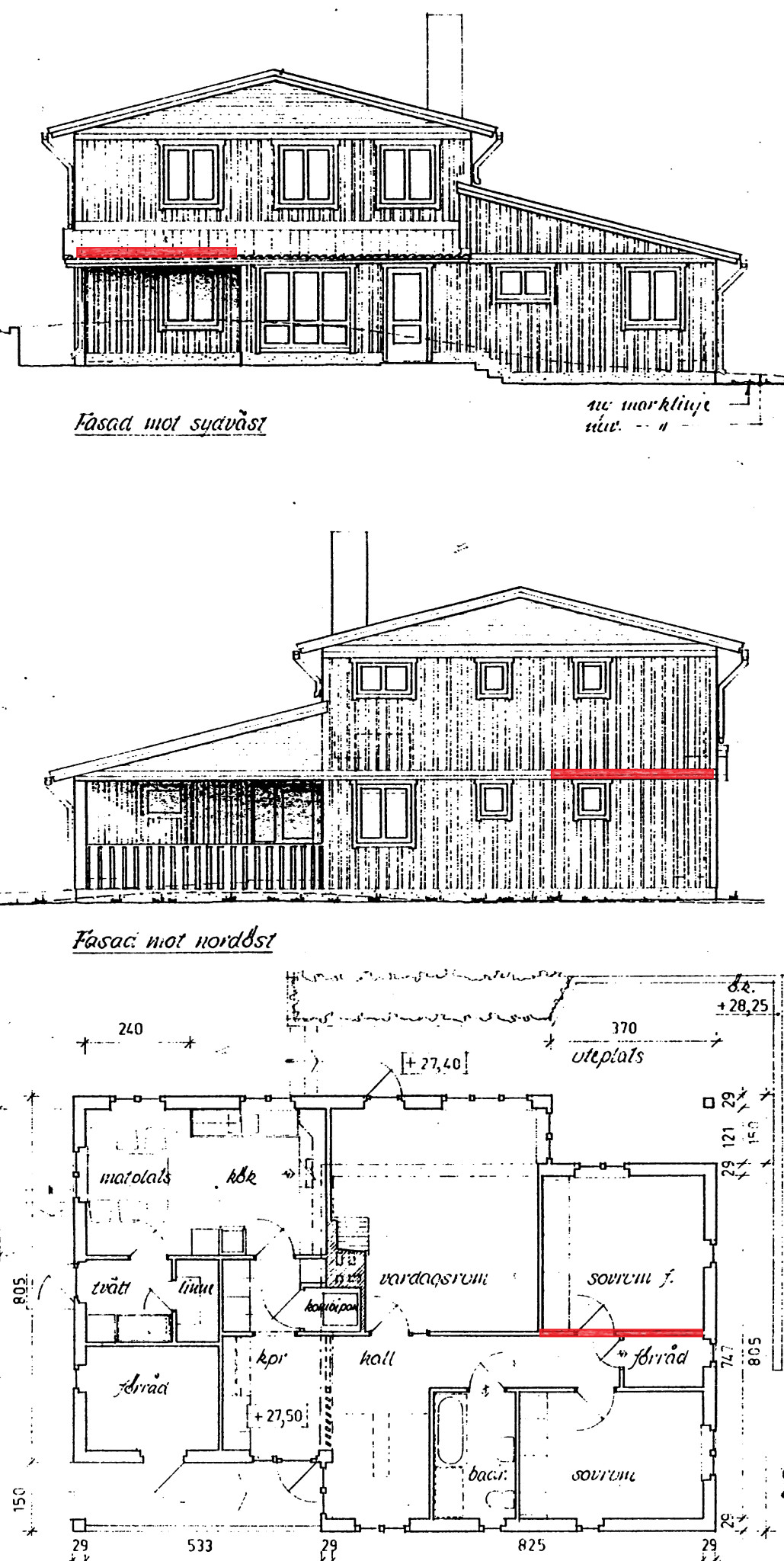
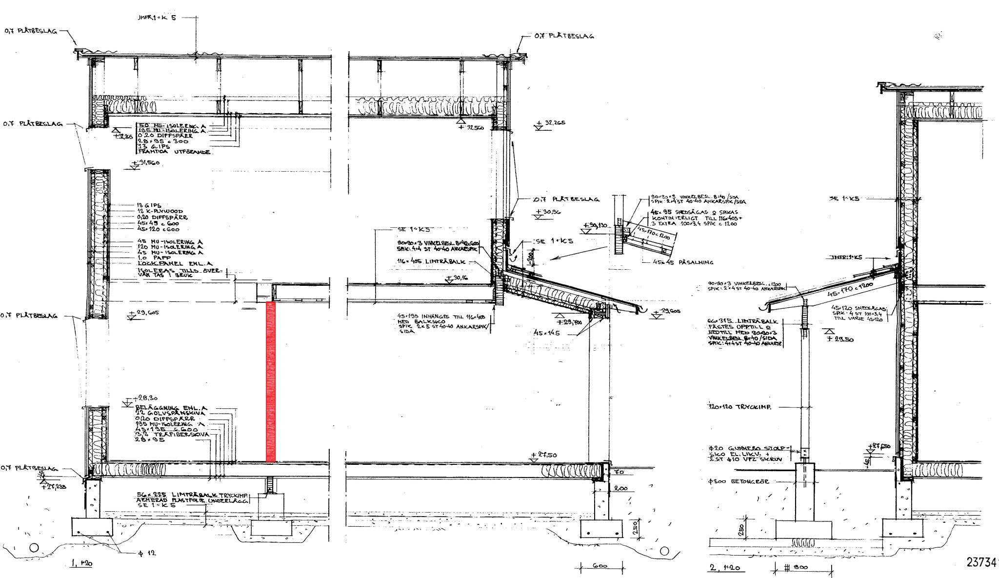
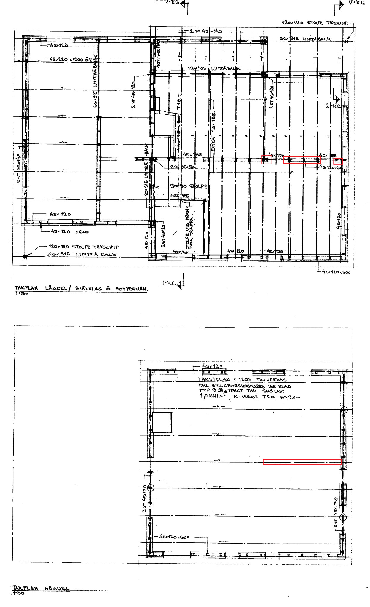
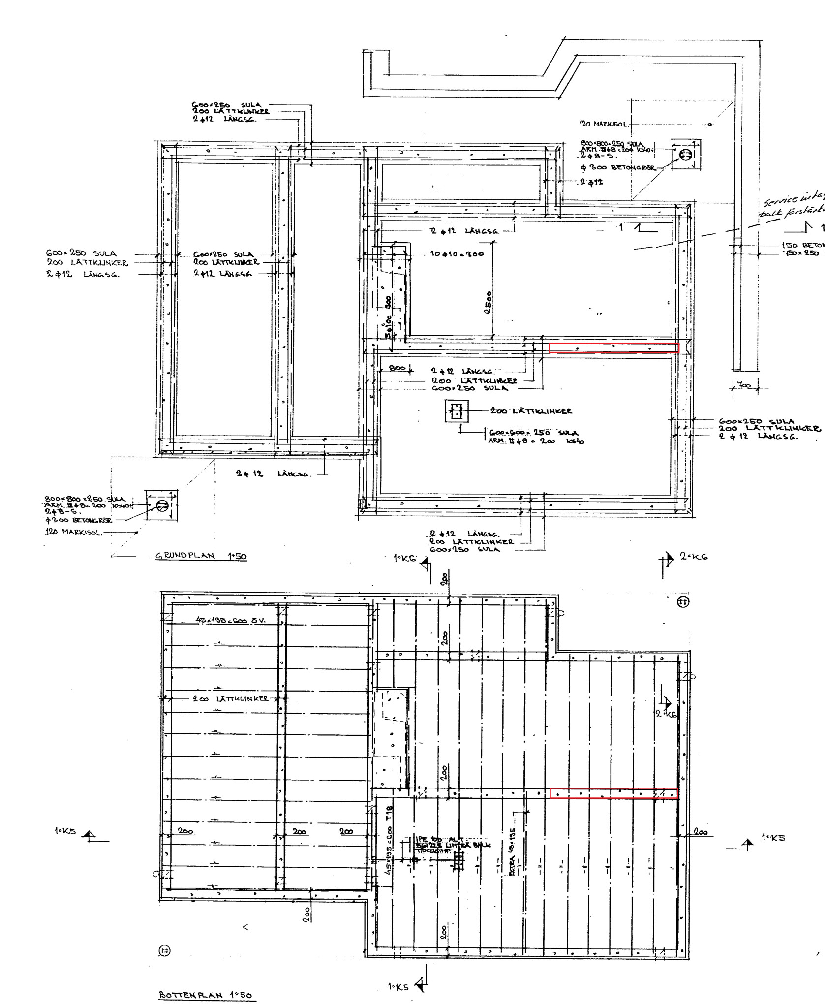
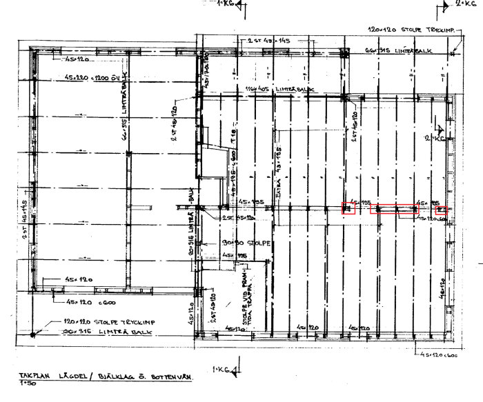
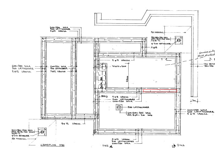
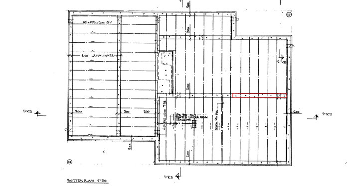
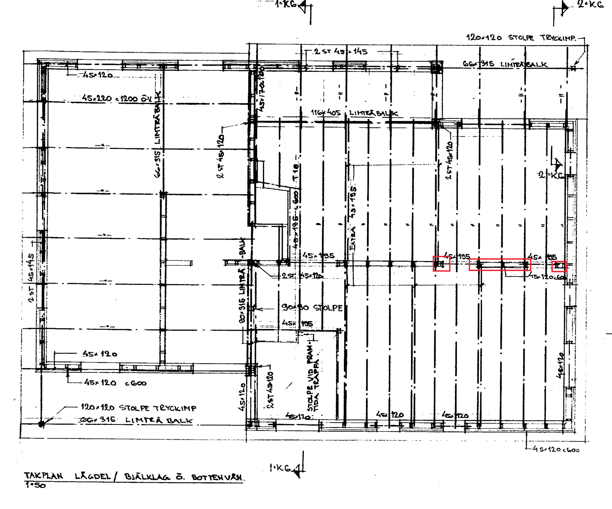
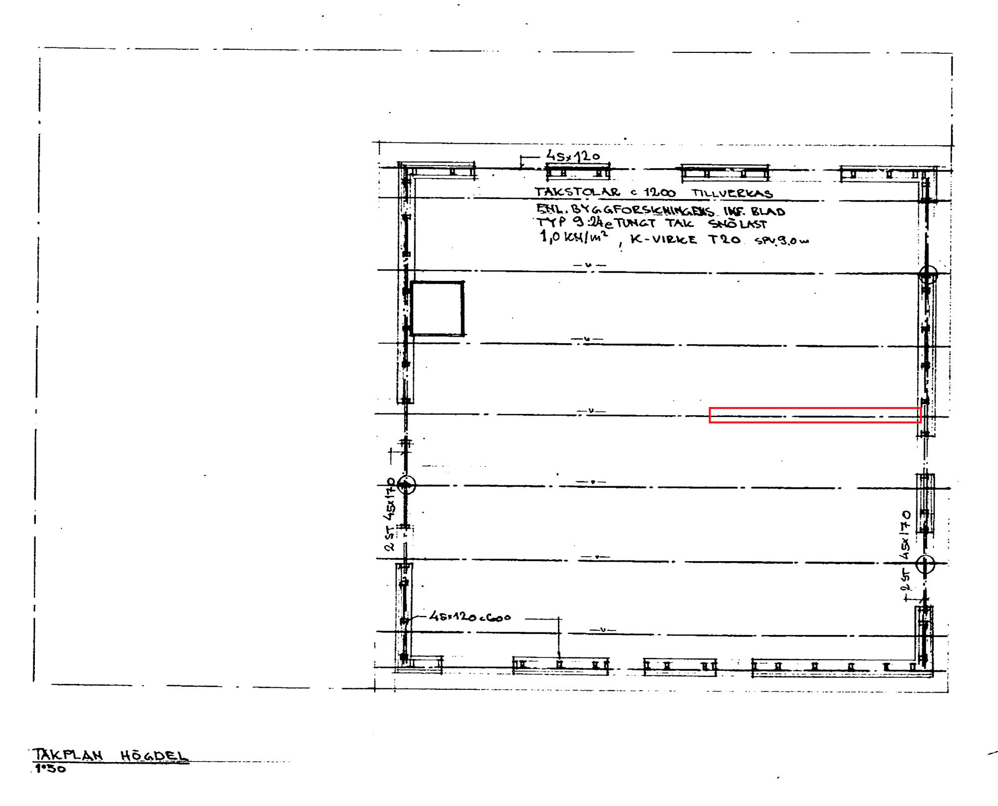
Thank you for the answers, it clarifies a bit at least what I am up against. I received a whole "bunch" of drawings from the municipality today and I'm uploading some of those I believe are relevant here.
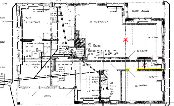
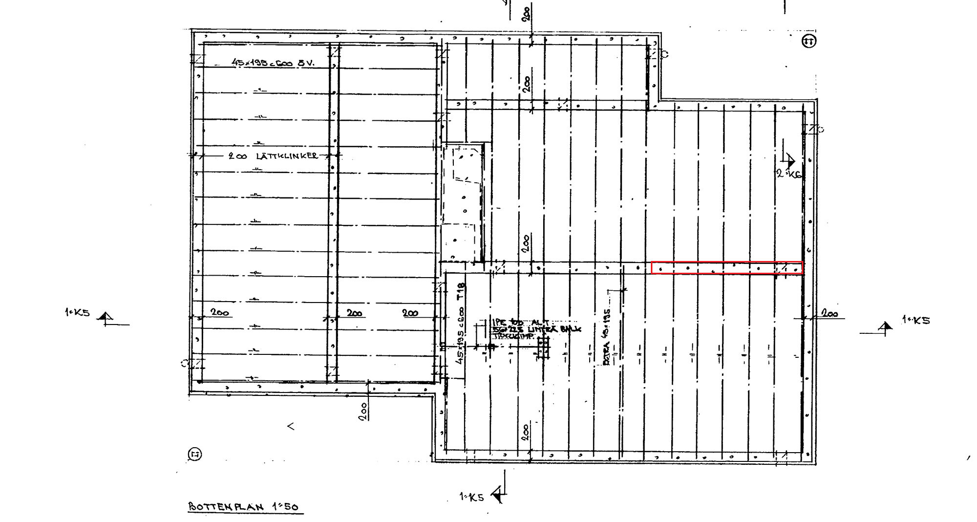
I have marked in red where the part of the hjärtvägg is that needs to be replaced with a beam. Blue is a new wall.
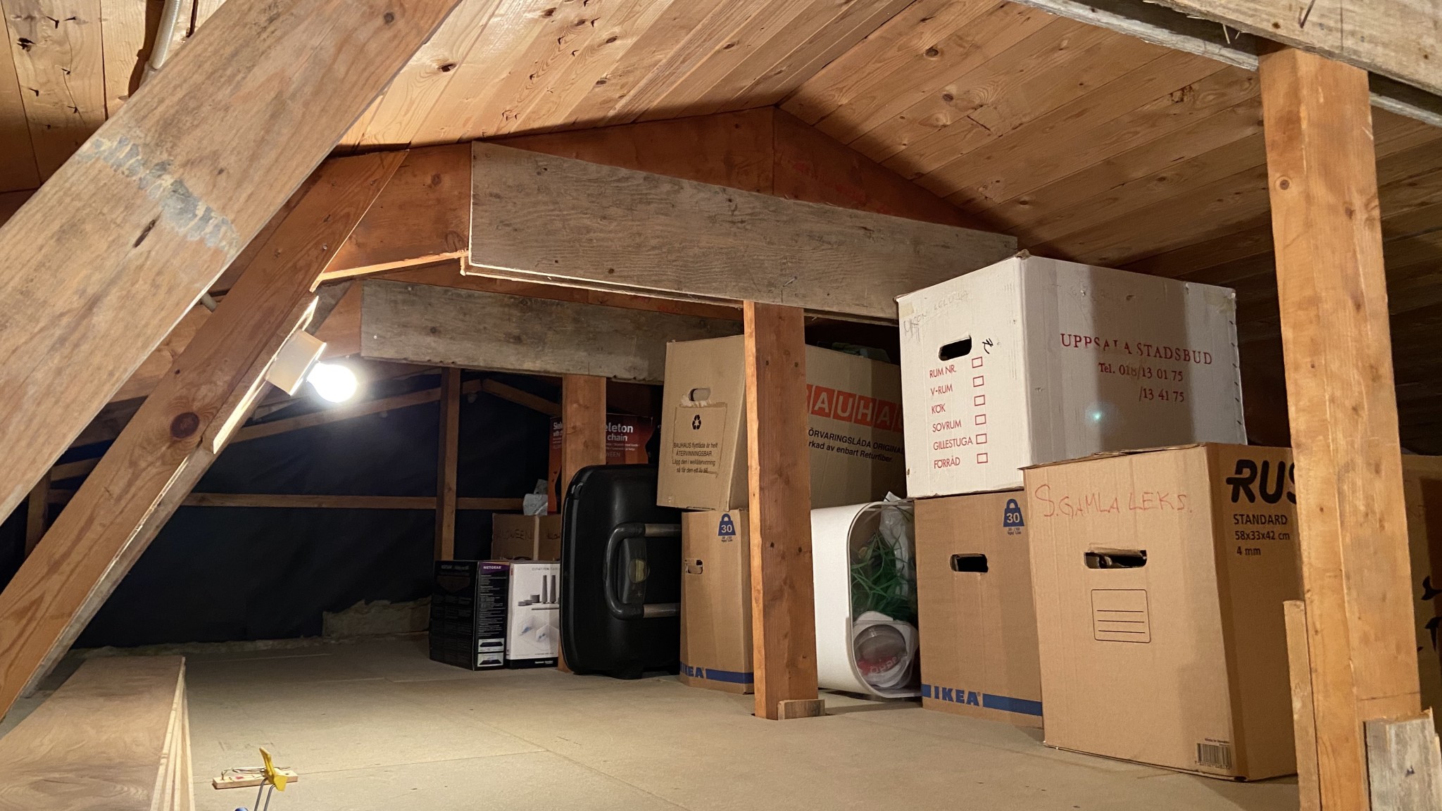
I don't know if these drawings clarify anything since I myself find it difficult to see/understand whether the hjärtvägg is supporting any part of the roof or not... I went up to the attic to see how it is there but didn't get much wiser.
We have four glulam beams of various kinds in the house as it is, but these are all on "external supporting" parts.
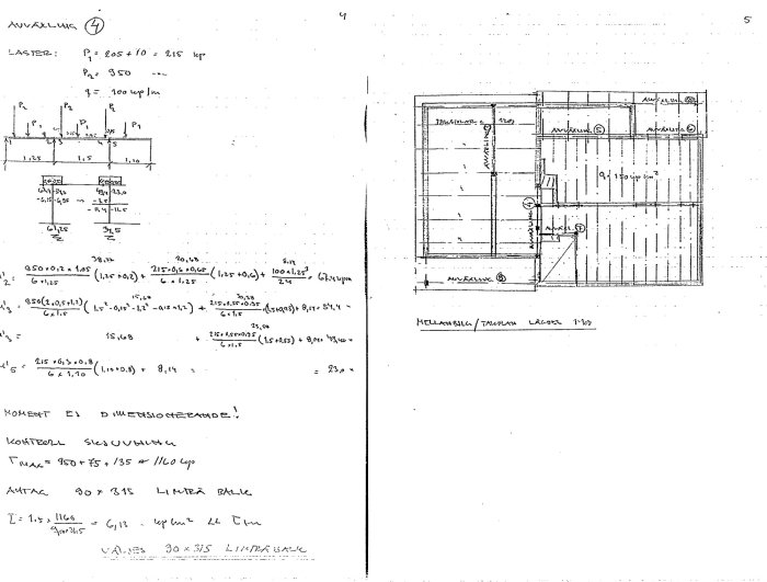
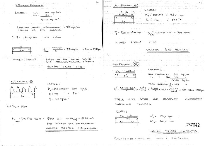
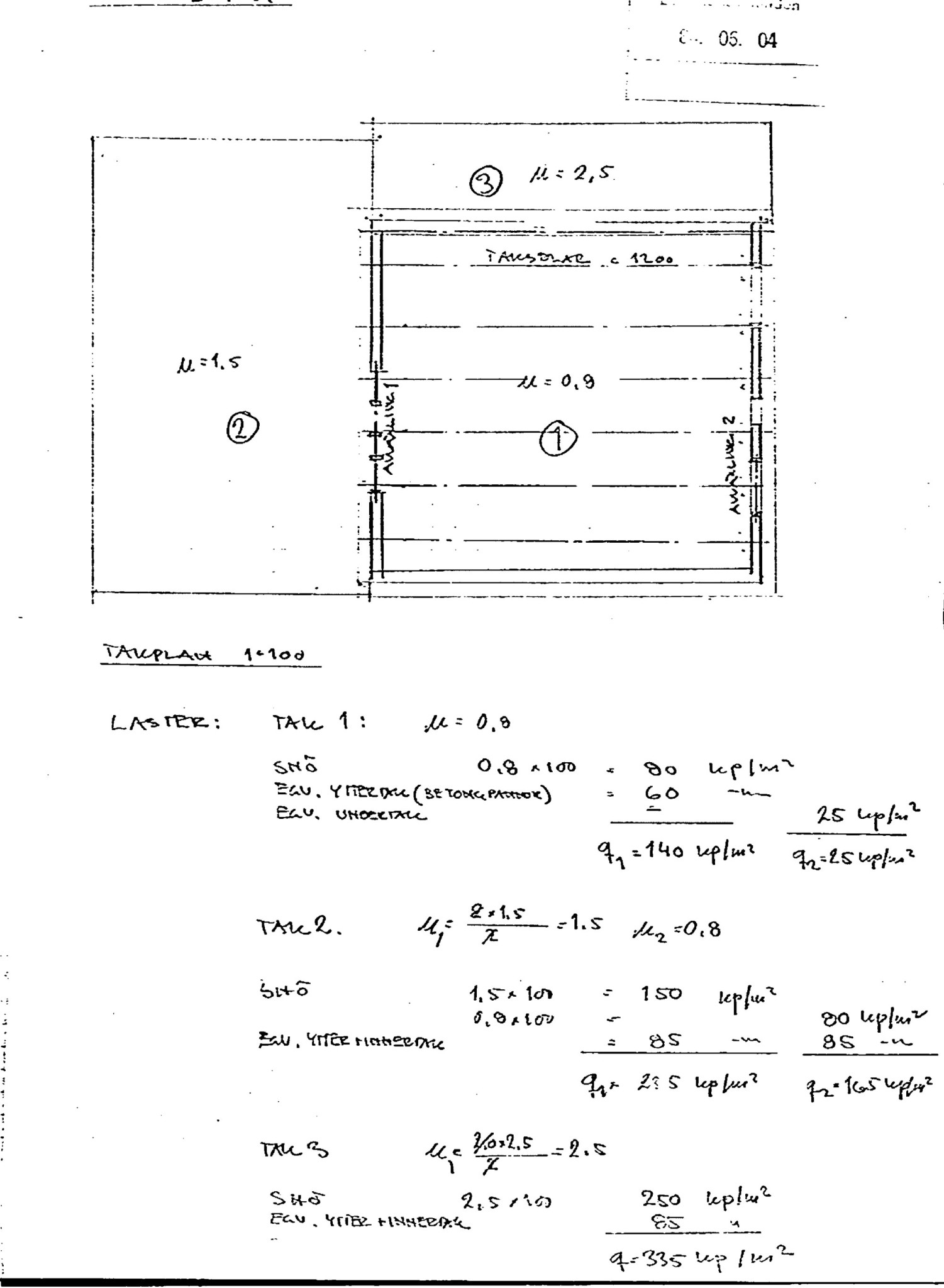
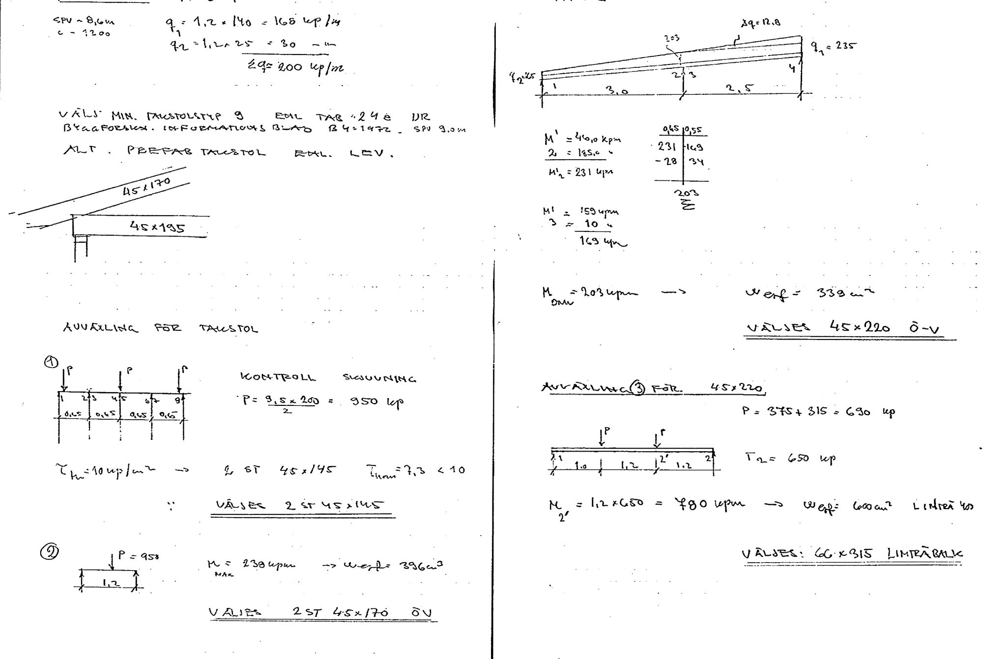
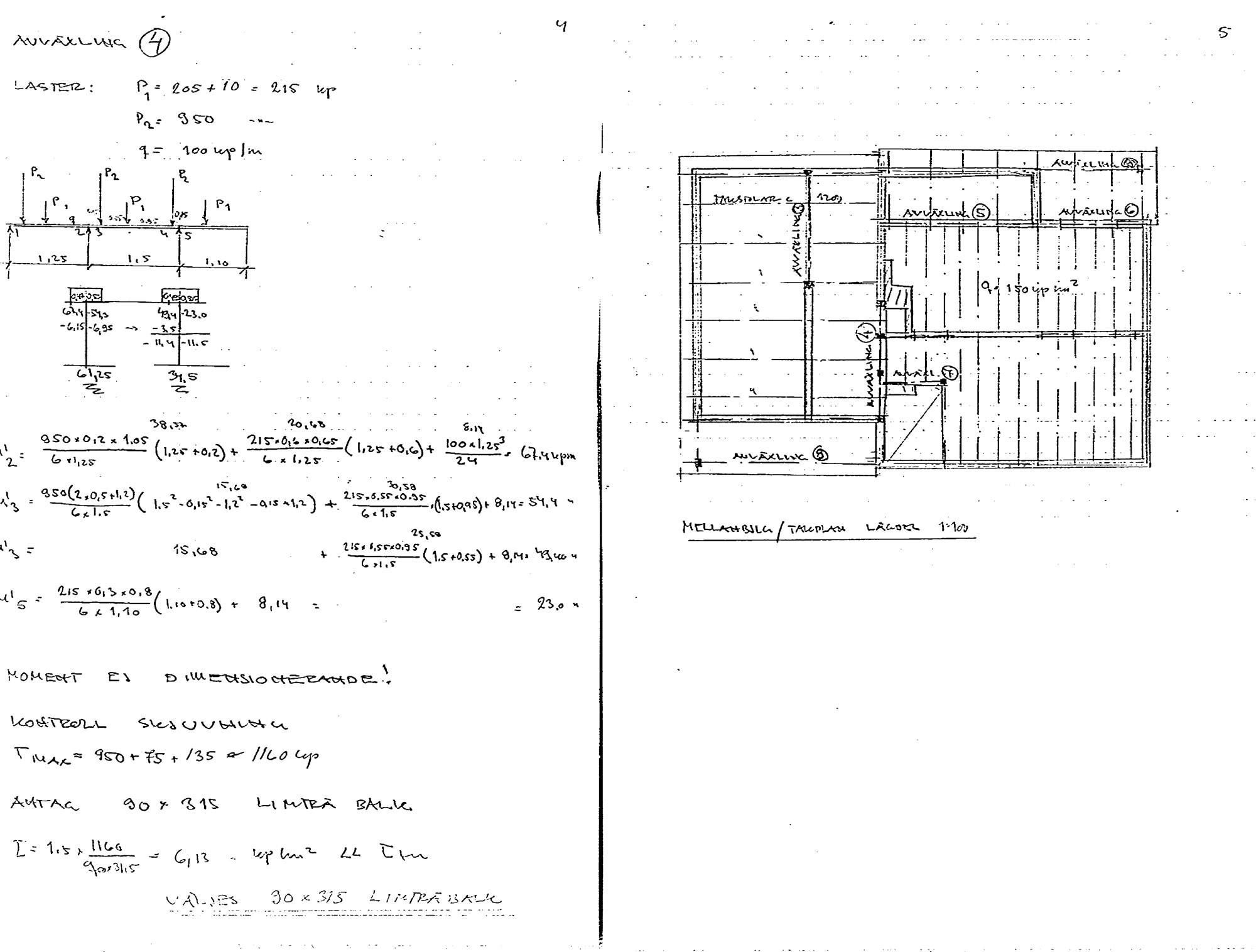
It is an originally built house! Unfortunately, the drawings are quite blurry. It is difficult to see the exact measurements. The load on the glulam beam is probably around 12 kN/m. This points towards a 215x270 mm beam. But as mentioned, this should be checked against drawings that can be measured.
Solid package from the municipality and exactly what's needed.
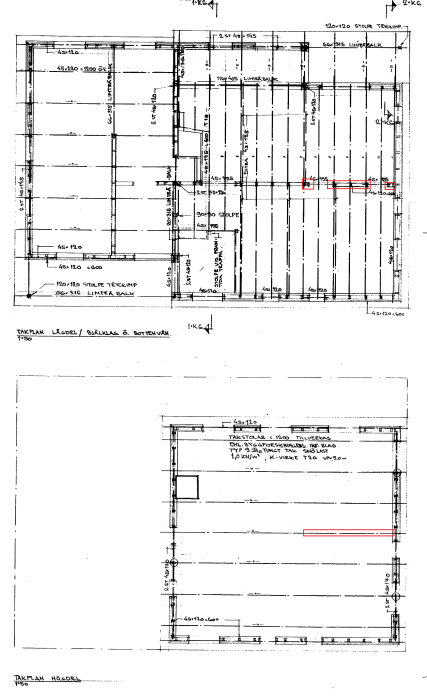
From what I can see, the rafters are parallel to the wall you want to remove, thus only the wall should support the floor above.
I only see a total measurement between the outer walls, but it looks like it's approximately the same distance from the wall to be demolished to the facade on both sides of the wall, about 4 m, can that be correct?
It is true that the rafters run parallel to the central wall and it is exactly 4m on each side of it.
I will try to fix the pictures so they are not so blurry, I received them in TIF format and had to save them in a different format and make them smaller to be able to upload them, but it didn't turn out completely well. I'll try again tomorrow.
I Googled quickly and it doesn't seem easy to get a 215x270 beam, I might have to choose 115x315 after all. But as I said, with better pictures, it might become a bit clearer and provide a better insight into the whole thing.
Why glulam beam?
We have a 5-meter opening where the central wall has been replaced with a HEA steel beam 5400 mm long, which is 200 mm high.
It is inside the floor structure and not visible at all.
Take a steel beam, and it will be much less obtrusive. And the steel beam can be clad in wood or something else, so you don't have to see it.
Regarding HEA beam, it is also not excluded, if it turns out that the glulam beam ends up at 315mm and an HEA beam at around 200 + plaster, it is definitely an interesting option.
Make another attempt with some of the images to see if they turn out better.
215x270 is a special order item, but no problem to obtain. Steel beams work very well when they can be built into the flooring. In this case, they are an unnecessary complication that is also expensive. TIFF is a troublesome format if you can't compress. The files become extremely large.
So it's 215x270 that's applicable in my case regarding glulam? I can also mention that there's a metal roof on the house nowadays, not roof tiles as in the drawing.
If you want the lowest possible glulam beam, it is 215x270. There are always alternative and equivalent dimensions of glulam. That's one of the great advantages.
From a load perspective, 90x90 is sufficient, but the dimension should be chosen with regard to the beam's width to ensure a reasonable support. Note that the columns must be placed on points that can withstand the large point load, which is nearly 30 kN, i.e., about 3 tons each.
Click here to reply
Vi vill skicka notiser för ämnen du bevakar och händelser som berör dig.