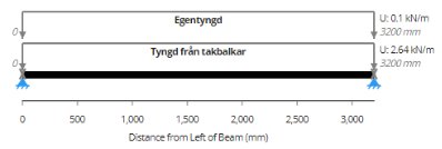
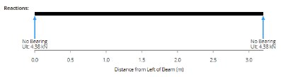
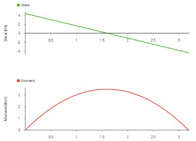
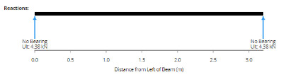
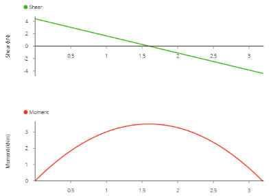
I want to create a recess in a load-bearing exterior wall. 3.2m of the exterior wall below will be replaced with 90x180 mm glulam (somewhat oversized as it will become glass sliding doors underneath) standing on two pillars 115x115 mm. I have q= 2.64 kN/m over the support beam from roof beams (self-weight + snow load) - calculated it to theoretical values kN/m, it is actually point loads. I get the following load cases against the beam:
Now to my questions:
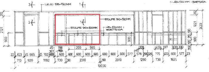
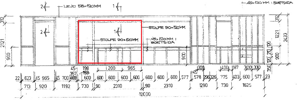
1. Where should the support beam be placed in terms of height in the following wall? Can it be placed above the red rectangle, directly under the handrail/main line?
Question 2. Should the pillar rest on the sill or should the sill be cut out where the pillars will sit? (I assume the first but asking to be sure).
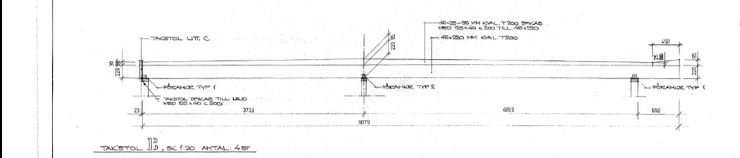
Question 3. How do I check if the concrete slab as shown below can handle the new pressure from the pillar? It is only 0.35MPa but I want to be sure. If anyone knows how to calculate it, a description of the calculation process would be appreciated, as I want to learn as much as possible.
2.64 kN/m is an unrealistically low distributed load in that context. Without knowing the roof construction and snow zone, I think the value should be in the range of 8-16 kN/m. As @Gabbe1 points out, 90x180 won't suffice. A more realistic dimension is 90x315-360. Then the column pressure will also be different, probably in the range of 1-2 MPa. If the columns land on the edge beam, there should be no problem, otherwise, some form of reinforcement is required. The sill should be cut away. It's probably better with 90x90 columns that can land with a larger part on the edge beam. From a load point of view, they are sufficient.
2.64 kN/m is an unrealistically low distributed load in that context. Without knowing the roof structure and snow zone, I think the value should be in the range of 8-16 kN/m. As @Gabbe1 points out, 90x180 won't suffice. A more realistic dimension is 90x315-360. This will also change the column pressure, probably in the range of 1-2 MPa. If the columns are on the edge beam, there should be no problem, otherwise some form of reinforcement is required. The sill should be cut away. Probably better with 90x90 columns that can have more on the edge beam. They are sufficient from a load perspective.
Thanks, you located the error in my calculations. New calculations can be found in another response further up. Furthermore, your explanation of the load distribution on the edge elements makes me consider replacing the beam and columns with something 90mm deep (as long as it can withstand the wind load).
Do you know where the beam should be placed in the wall? Cut away the existing beam over the window and place the support beam directly under the bearing line?
And what type of foundation reinforcement might be necessary in a case where the column does not sit on the edge element?
2.64 kN/m is an unrealistically low distributed load in that context. Without knowing the roof construction and snow zone, I think the value should be in the range of 8-16 kN/m. Then 90x180 doesn't suffice as @Gabbe1 points out. A more realistic dimension is 90x315-360. Then the column pressure will also be different, probably in the range of 1-2 MPa. If the columns land on the edge beam, it shouldn't be a problem; otherwise, some form of reinforcement is required. The sill should be cut away. Probably it is better with 90x90 columns which can have a larger part on the edge beam. From a load point of view, they suffice.
The stamp pressure becomes too high (support beam against stud 90x90). Must increase to columns 115x115 to withstand the stamp pressure. How do I check that the foundation holds now that the beam lands a bit away from the edge element? Note that the remaining columns in the wall are of dimension 90x120. So the column will be in the right place, but the pressure will increase. Therefore, I think a calculation check is required.
Click here to reply
Vi vill skicka notiser för ämnen du bevakar och händelser som berör dig.