Eurocode now applies, absolutely. At this point, it doesn't matter for evaluating different suitable dimensions. In the event of a building permit, however, the beam would have to be verified according to EC.
Sorry for not joining your discussion, I feel like I can't contribute anything meaningful there anyway =)
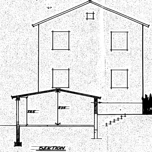
What I have managed to dig up, however, are the building permit drawings, even though they didn't need to be so detailed in 1959... It states that the foundation method is concrete stone, that the walls consist of 25 cm light concrete, and that the roof consists of 3" x 4" cc 60 cm with support on limited walls. Between the rafters ...(illegible)... boards + maintenance-free felt on the outside, boards + 12 mm gypsum boards on the inside. CC is therefore less than what I initially indicated.
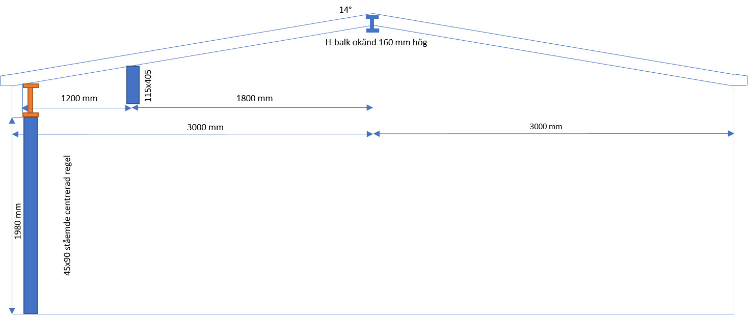
Could one imagine a solution where I place a glulam beam/steel beam a bit into the garage, drawn into this sketch at 1200 just for illustration and thus buy a bit of margin?
I also attach some pictures from the building permit documents, maybe someone with better eyes or imagination can decipher what it says after "Between the rafters" =)
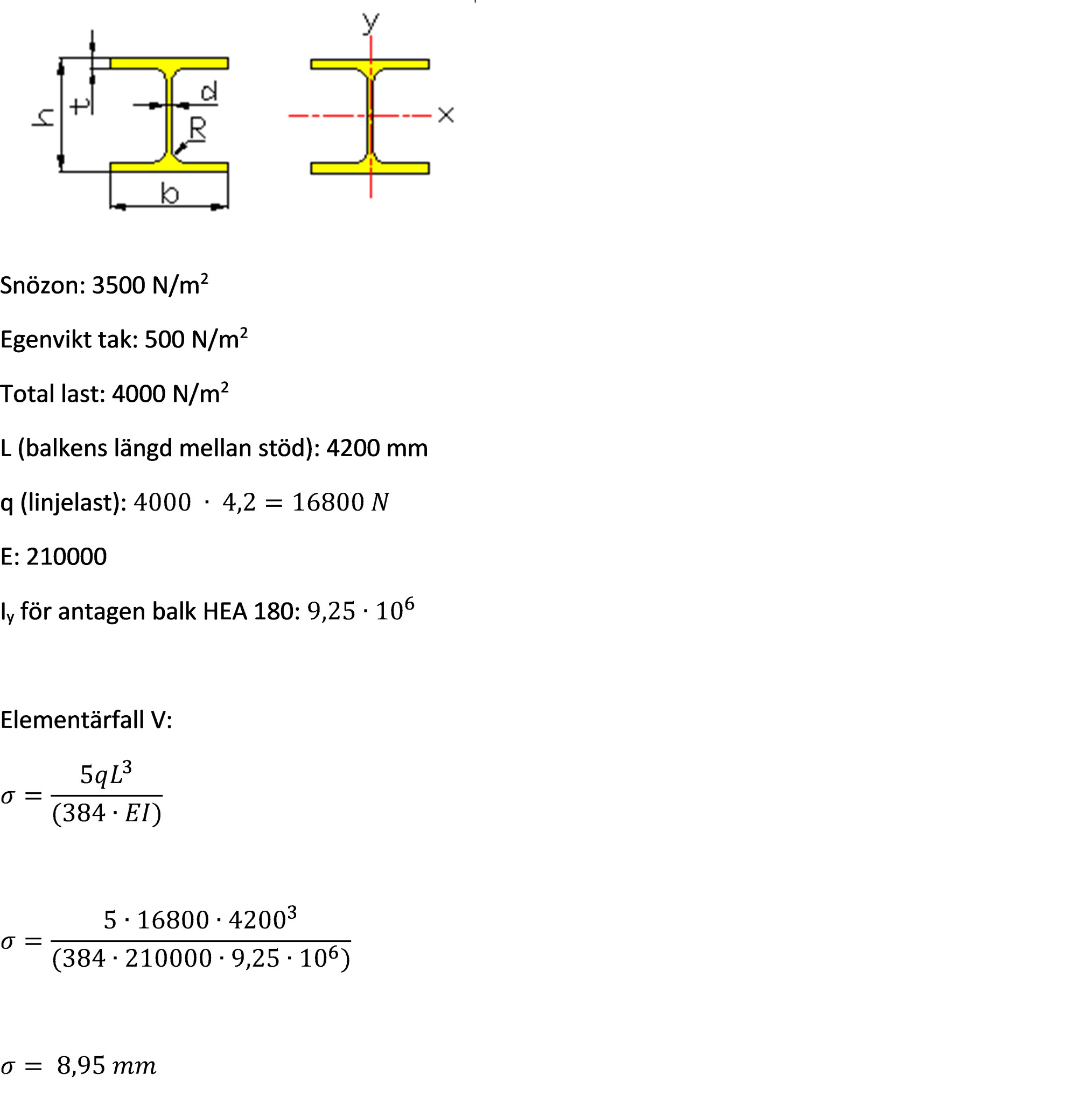
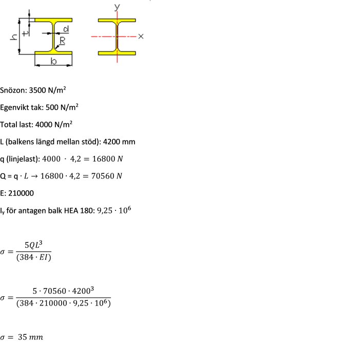
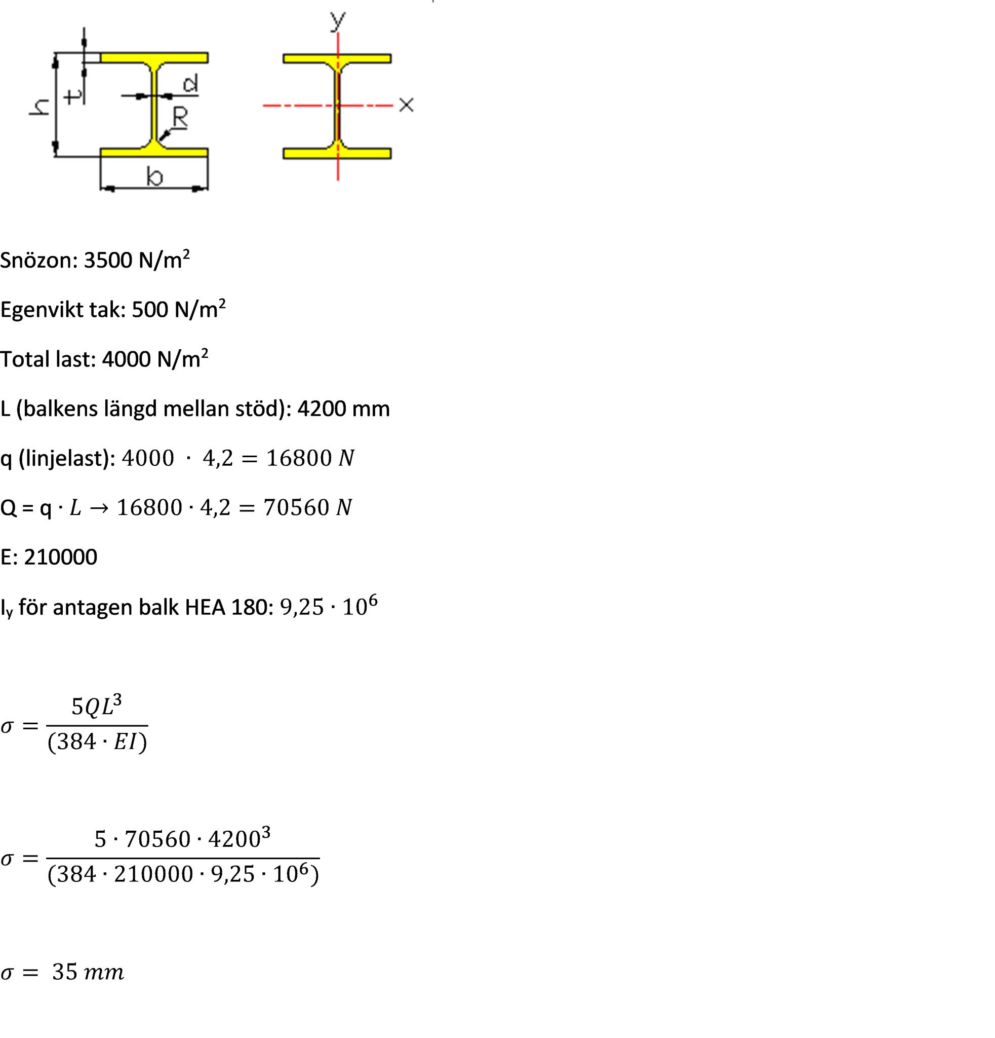
Although the formula states L^3 according to the formula collection, I missed the difference between q and Q and the formula should contain Q (= q x L): 16800 x 4.2 = 70560 N.
(checked here:
)
Then I get the following, which seems a lot...
However, I'm unsure about the calculation of line load, having received different tasks there with the roof area taken into account or not, with 25% of the roof weight towards the current beam, etc.
Looked at this calculation example: http://pl.fredrika.se/konstruktion_filer/bron/nedbojning av u_balkarna.htm
and there the total load x length was used.
In the calculation of line load, it is not the length of the beam you should use but the width of the roof that loads the beam. If, for example, you have the beam in the facade line, the loaded width becomes 1.5m, i.e., half the distance between the facade and the ridge beam. If you place the beam further in, the loaded width becomes somewhat larger due to the continuity of the roof rafters.
Ok! I have concluded that the beam will be placed in line with the facade since otherwise I would take up too much depth in the garage as the door will be on the inside of the beam. I assume we are still talking about widths in a flat position and not along the roof slope?
If I then calculate based on 1.5m, the line load q: 4000N/m2 x 1.5 = 6000N and
Q thus: 6000 x 4.2 = 25200N. This in turn gives the numerator: 5x25200x4200^3 which results in a deflection of 8.66 mm.
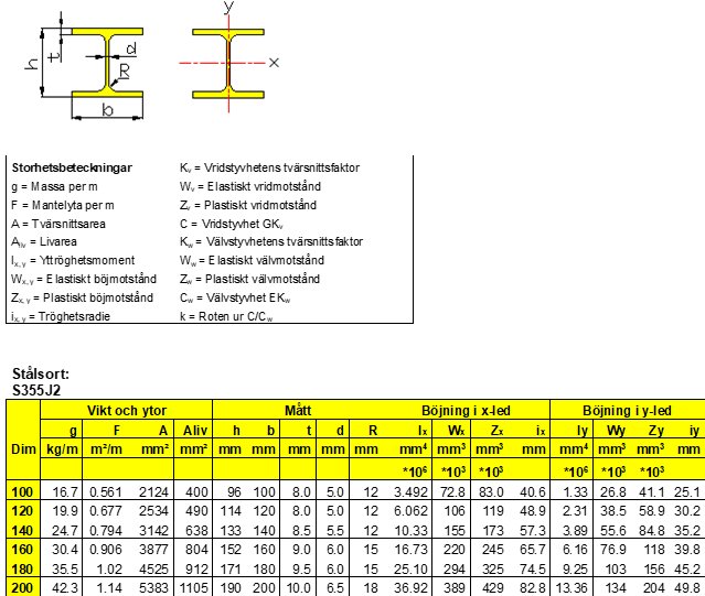
A line load of 6 kN/m is also what I used in my latest calculation. In my steel table (Tibnor's), HEA 180 has an Iy of 2510x10^4, i.e., 25.1x10^6. If you use this value instead, the deflection becomes 4.6 mm.
I think you're ambitious for tackling this, but bossespecial is also an excellent mentor.
Thanks for the encouragement!
I think both of you have been excellent inspirers and mentors!
I have taken the values from begroup's Excel archive, and they only use x and y as below (and above). Could it be that Tibnor's y applies to a different direction, as it exactly corresponds to begroup's bending in their x direction?
In any case, those millimeters have no real significance in my case, just an interesting subject!
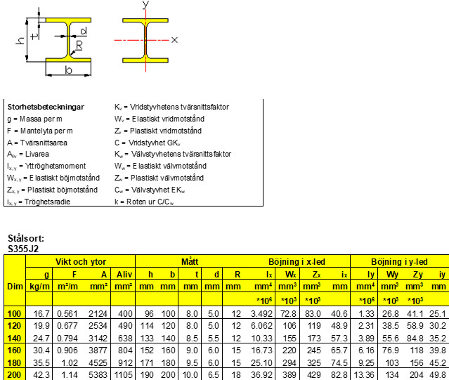
Strange. With this table, you should use the value for bending in the x-direction. In Tibnor's table, it is called bending in the y-direction. In any case, it is the higher value of the moment of inertia (I) that applies. You can verify this by roughly calculating these values. Use the formula bxh^3/12. Start with the outer beam shape and then subtract the areas that are empty. Then rotate the beam a quarter turn and redo the calculation.
It is probably an old Excel table that has not been updated. In Tibnors' old tables and old BSK, bending around the x-axis was used as the rigid direction, which was changed with Eurocode to the y-axis.
I actually didn't remember that. But now when I looked at Tibnor's table I saw that bending in the weak direction was called bending around the z-axis, which I hadn't observed before.
Let's see if I understood you correctly... however, I'm not quite sure how it shows that the higher value should be used. Not because I in any way distrust you, rather because I want to understand.
Air: (180-6)x(171-19)=26,752
Beam dimensions in initial position: 180x171^3/12 -> 180x5,000,211/12=75,003,165
75,003,165-26,752=74,976,413
Spontaneously, when I look at the beam, I perceive it to be stiffer in the joint where it stands like an upright H due to two supports on edge compared to a horizontal H where only the web provides support. Is this what you refer to as the stiff (upright H) and weak (horizontal H) direction?
I think a light bulb just went off here! The bending is around the axis and not in the axis!(?) Then bending around the x-axis means the deflection of the flanges.
Let's see if I understood you correctly... however, I'm not quite with you on how it can show that the higher value should be used. Not that I distrust you in any way, but rather because I want to understand.
Air: (180-6)x(171-19)=26,752
The beam's dimensions in the starting position: 180x171^3/12 -> 180x5,000,211/12=75,003,165
75,003,165-26,752=74,976,413
The air should also be calculated as bh^3/12, you haven't included the cubic term in your calculation. And you have to calculate the air differently depending on which axis you're considering, even if it's the same cross section that should be subtracted from the moment of inertia, what is considered the width and height changes depending on which axis is considered.
Vi vill skicka notiser för ämnen du bevakar och händelser som berör dig.


hordak said:
Let's see if I understood you correctly... however, I'm not quite with you on how it can show that the higher value should be used. Not that I distrust you in any way, but rather because I want to understand.