Hello,
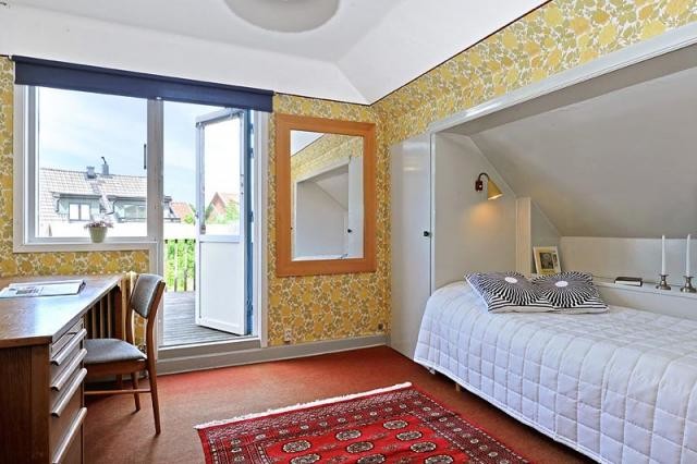
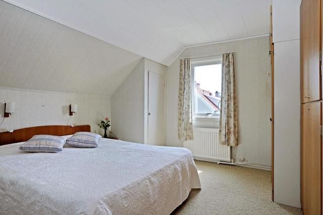
We get access to our house in September and planning is underway. We have two rooms upstairs with closets in the corners, see attached images. I have received some different information that the walls of the closets "contain" support posts for the roof trusses and the space in between is offloaded (where the beds are located).
Is that possible? We would like to remove both closets, especially in room B (b_room.jpg) and possibly in room A. Is there a way to do it?
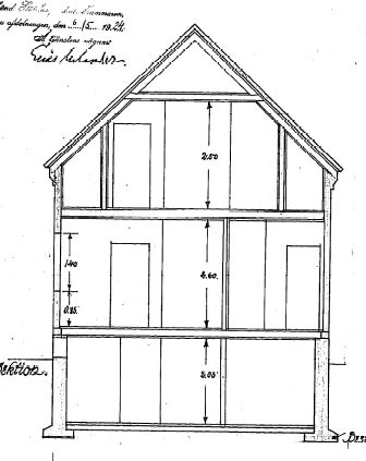
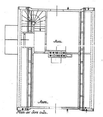
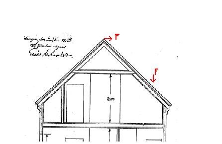
The house is from 1924 and has been rebuilt in stages. I am attaching the original drawing.
Thanks in advance!
We get access to our house in September and planning is underway. We have two rooms upstairs with closets in the corners, see attached images. I have received some different information that the walls of the closets "contain" support posts for the roof trusses and the space in between is offloaded (where the beds are located).
Is that possible? We would like to remove both closets, especially in room B (b_room.jpg) and possibly in room A. Is there a way to do it?
The house is from 1924 and has been rebuilt in stages. I am attaching the original drawing.
Thanks in advance!
then it becomes quite difficult to follow the formula from https://www.flashback.org/t713271 therefore you can have some candy reading like http://www.sbi.se/uploaded/dokument/files/Art_Dimensionering%20av%20branta%20tak%20-%20F%F6renklad%20ber%E4kningsmetod.pdf
Thanks!jeffkan said:
My thought is more in the direction of, according to the house's construction, there should be "stödben" and they have already unloaded these with a load-bearing beam where the beds are located?
After researching a bit for my own extension with raised wall plates, it seems there are three ways to ensure such a roof truss construction doesn't collapse:
1. Support struts
2. "Hang" all the trusses on a sturdy beam at the roof ridge.
3. Ensure there are sufficiently rigid joints. Only one of all the truss manufacturers I spoke with thought they could achieve this, which makes one wonder if it's possible.
I've seen a number of old houses without support struts (i.e., the rooms on the upper floor are as wide as those on the lower floor, so there can't be support struts as far as I can see), and I guess they have a solution with a sturdy ridge beam, i.e., solution 2.
If you look at the drawings, it definitely looks as if there originally were support struts for the trusses, even where there are now sleeping alcoves.
Admittedly, they used to over-dimension back then, but if the construction was originally designed with support struts, I would guess they are a prerequisite for durability and that they only relieved the load at the sleeping alcoves and that the support struts remain elsewhere.
But this is amateur speculation; you must talk to an engineer before doing anything drastic, of course.
Since I myself have an interest in this, I continue, excuse TS. Is it to prevent the roof trusses from separating at the ridge due to bending forces on the rafters that they are attached to a beam at the ridge (see sketch). Shouldn't the rafters also be reinforced at the same time? And these forces are very dependent on the span and roof pitch, right?
No, the beam should prevent the podiums from collapsing under the extra angle brought by the elevated wall plate. It rests (in my case because that was the solution) on two standing laminated beams, one at each gable, and the rafters are kind of threaded on it at the top, so it’s actually not at the roof ridge but just below it.
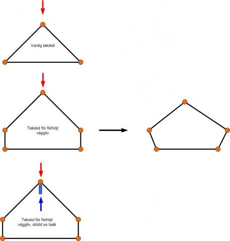
See the attached image, which shows a couple of rafter models. They are assumed to consist of some sort of ideal studs that neither break nor bend (thus no upper arm is drawn). However, the joints have zero rotational stiffness, meaning they bend like hinges.
The typical triangular truss is still stable, even if the roof's weight pushes down on it.
The podium with elevated wall plates, on the other hand, collapses immediately under weight from above.
With support from the beam (blue rectangle in the last picture), the collapse is counteracted, with the weight being taken up by the beam.
With real trusses, of course, the joints aren’t hinges, but the trusses and the beam work together to support the roof's weight.
In old houses, I assume the standing laminated beams are replaced by gable walls made of solid wood.
Last edited:
It's probably best to ask a designer about that.
In the simplified two-dimensional world consisting of lines, dots, and arrows that I drew up, it's quite worse with an outer wall made of log timber, but in the real world you could certainly be right.
(My note about old houses with massive wooden walls was about the solution with a beam in the ridge and, as mentioned, was just an assumption!)
Last edited:
Click here to reply