Thought a bit more... If the current beam takes up the force x N in the horizontal direction and is replaced with a rule that has a 20-degree slope, then the resulting force in this rule should be
x/cos(20) = 1.06x, i.e., 6% higher
Considering the dimension of the current beam, the fixing is likely the weak point and all I need to do is:
1. Create a fixing that is 6% stronger than the existing one. This shouldn't be a problem since I'm also adding more.
2. Not have issues with the rafters being pulled apart by the horizontal forces. This is not likely since I'm making an 'A' with nail plates, etc., etc.
Vertical forces, which I thought would be the biggest problem, don't seem to get much reaction?
One must probably remember more things here and in log houses, everything interacts. The horizontal logs you have are probably intended to hold together the exterior walls as their primary function. Then they have been used as supports in a truss construction. Removing the logs is therefore about a bit more than just supporting the roof.
Now a coin has dropped. The force on the outer wall arises because the trusses bend and press on the outer wall, I guess? So if I have infinitely strong trusses and 90-degree walls, then I get 0 net force on the outer walls. In practice, of course, I don't have 90-degree walls, but the net force should still be minimal as long as the trusses don't sag.
However, when they do sag, they press heavily on the top beam.
But from the above post, it doesn't sound like anyone is pointing out this phenomenon, but rather that the walls should hold together when you have a 4.5m open room... hmmm Can someone explain this?
Yes, but you don't have a roof truss in that sense, even if a combination of braces could now allow one to say that you have one. You erect exterior walls. You place logs that hold the walls together. Then posts and ridge, then braces that support the roof and together you have a construction that supports the roof and holds the walls together. If you then want to completely remove the logs that hold the walls together (I almost understand it as if there won't be any left), then you really need to think about what you're doing.
I want to remove a beam. Then there are lots of small "beams" that the ceiling was nailed into that of course contributed to holding things together, but my new rafters will contribute. They will also be placed closer together and be better attached than these, where some came loose just when I broke down the tongue-and-groove in the ceiling because it wasn't particularly tight.
Can someone give an idea of what forces we're talking about to hold the walls together and the source of these different forces?
Okay, looking at one of the drawings (that I missed), I don't think there is any major problem with doing it as you wish IF you make sure that the timber that may then be in the room's exterior walls really runs from wall to wall. The one by the chimney stack must also run uninterrupted between walls, so they really hold together. Perhaps even reinforce with something so that they are really fastened to the walls.
The point is that the old construction method often means that the load goes diagonally with the roof and in that way pushes the walls outward. A modern construction method with a truss means that the truss bears the roof's weight and the entire weight then rests on the walls, and the force goes straight down into the wall, and they are not pushed outward in the same way.
Yes, the walls will be held together with A-trusses that will be securely anchored to both exterior walls throughout the open space. I will also keep the next large monster beam that runs across the house at the chimney.
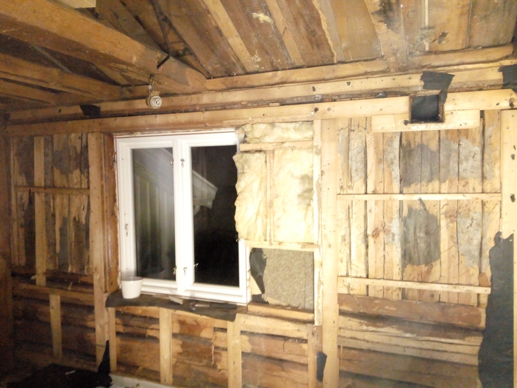
Torn down the outer wall I described earlier, a horizontal solid log on top of the stumps with standing timber. This log is connected with the other outer wall on each side of the room if I cut the middle log.
And why don't the A-frames with an 18-degree slope hold the outer walls together? For the walls to fall outward, the A-frames must be pulled apart.
I would have liked to see the cabin in reality, but nowadays I live quite far from Lindome. Old houses are rarely as systematically built as modern ones, so there is always an uncertainty when solving problems via photos and drawings.
A roof structure that rests on the outer walls and a ridge beam does not need a collar beam to prevent the outer walls from being pushed out. However, there may be other reasons why a collar beam is suitable. Additionally, it may be that your outer walls need bracing in another way. The combination of horizontal and vertical timbers is not foolproof.
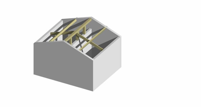
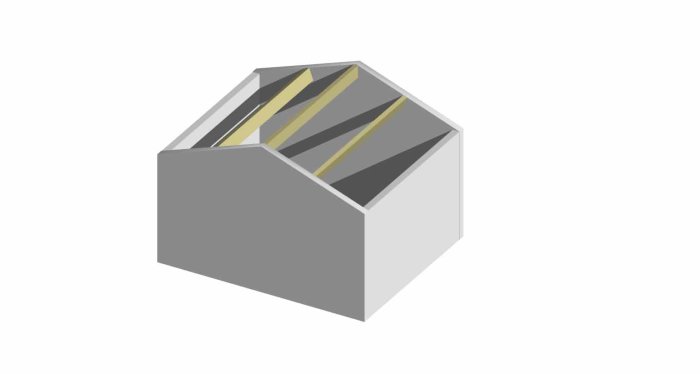
I have made two conceptual solutions that I have calculated. In the first example, I retain the current ridge beam and purlins. I replace the existing "half-trusses" with a strong roof beam each in the middle of the respective house section. These roof beams rest on the outer walls and the mid-wall and support the purlins. In my example, glulam in the dimension 56x225 mm is required for these beams. See the following image. In the second example, I replace all existing truss wood except the cover panel with three longitudinal glulam beams. A ridge beam and two purlins. These beams are assumed to be supported on the timber frame or through glulam columns. The dimension of these is 90x270 mm.
56x225 can be replaced by 115x180. 90x270 can be replaced by 165x225. This is a rough calculation since I do not have access to the exact measurements, but it gives an indication.
A vertical load affecting a stud with a 20-degree slope affects the stud in its transverse direction with a load that can be reduced by the factor cos 20°, i.e., 0.94.
Thank you for this, it's exactly these kinds of examples that give a good feeling. It should be added that it's a villa and the upper floor we're talking about, but that's probably of minor importance.
In your first case, you have only a laminated beam truss in the middle of the room, if I do it exactly the same way but with regular framework cc60, I should significantly reduce the dimensions, right? I have no reason to remove the existing truss either since everything will be insulated and built in anyway.
As justus mentions, the outer walls, with both horizontal and vertical timber, are not quite perfect. I myself live in an old plockepinn where I reinforced similar walls with new studs that I attached to both the floor and ceiling joists. The studs hold back any potential "wobbling" together with the joists. I wouldn't think your outer walls are straight either but instead leaning? This leaning will result in a horizontal load=leaning*vertical load on the wall. These are often small and can usually be handled in the sheathing. Now, you don't have a "real" sheathing, and I'm not quite sure how well these can handle the loads. Could you measure how much the wall is leaning so justus and others can get an idea of the loads?
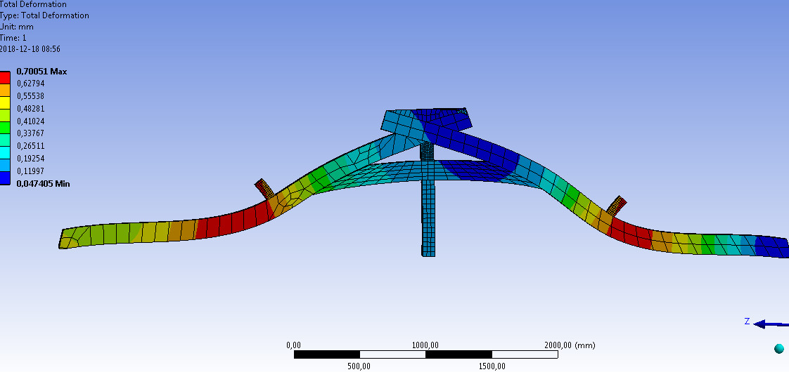
Entertained myself by calculating as well. Not a mechanical engineer but familiar with FEM and also well aware that the boundary conditions of the problem have their shortcomings...., "support" etc. etc.... should still give a bit I think
double 145 beams that have ideal contact (145s because every cm of these lowers the ceiling height and starts heading down towards the window...)
"frictionless support" under the side surfaces and under the pillar in the middle
7600MPa in Elastic Modulus for the wood
4000N from the ridge on a truss
2000N from each of the longitudinal beams
The model consists of ONE truss and the weight of the roof I have calculated as the weight of a 60cm section landing on this.
2kN/m2 in snow load
1kN/m2 for a tiled roof
a total of about 12kN (3000*0.6*(3.2+3.2))
From this weight, I guess an even distribution of the force, i.e. about 2000N directly on each outer wall where the truss rests, 2000N on each longitudinal beam, and 2000N on the ridge from each section =>4000N on the ridge
No consideration has been given to the fact that other parts of the construction take up weight, which of course works to my advantage.
Shortcomings? Absolutely, but something to start from. If anyone has input on what I should change for the calculation to be more accurate, it is appreciated!
Vi vill skicka notiser för ämnen du bevakar och händelser som berör dig.