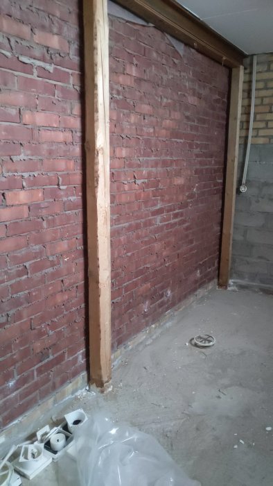
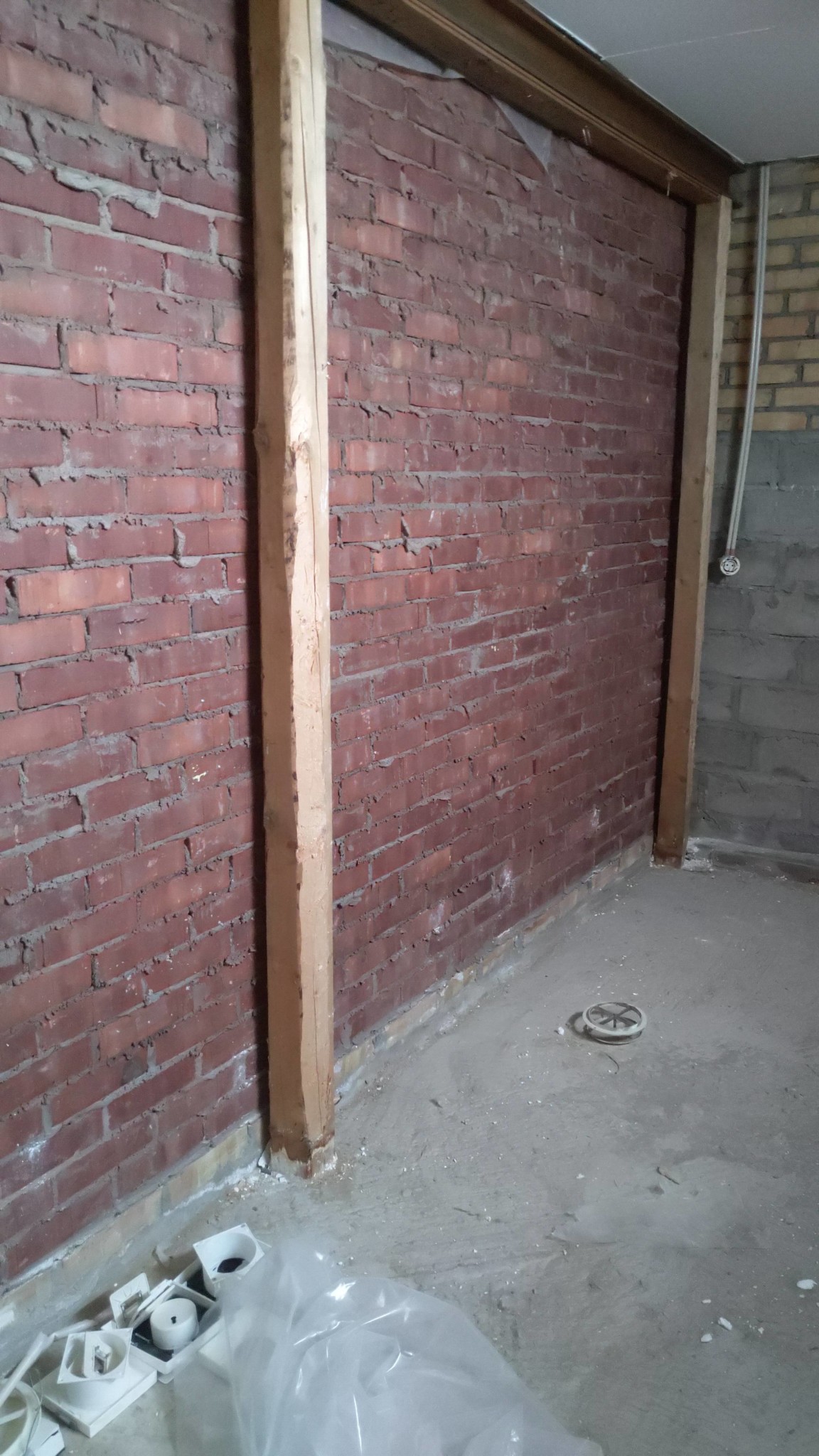
In our basement/lower floor, we have an I-beam as extra support for the cast intermediate floor. It rests partly on masonry partition walls and partly on timber posts that we want to replace because we want to remove all organic material. My idea is to replace the timber posts with 120*190*590 lecablocks stacked on top of each other. Will this hold?
There are 4 posts that need to be replaced. They are about 2 meters apart.
It is a somewhat peculiar construction. First, you should get an idea of the loads the beam handles and what type of beam it is (profile and dimension), at least if you want a more analytical approach. Drawings are the best basis.
It is a bit of a strange construction. First, one should get an idea of the loads the beam is supporting and what type of beam it is (profile and dimension), at least if one wants a more analytical approach. Drawings are the best basis.
Mm. Unfortunately, there are no drawings. Or yes, there are, but they don't match. According to the information, the intermediate floor was supposed to be wood, but it was changed. So it's a bit difficult... I could start by measuring the thickness of the floor and the dimensions between the load-bearing walls to be able to calculate the load... ?
I could start by measuring the thickness of the floor structure and the dimensions between the load-bearing walls to be able to calculate the load... ?
An excellent idea. Plus check the beam's profile in mm.
The floor slab is 160mm
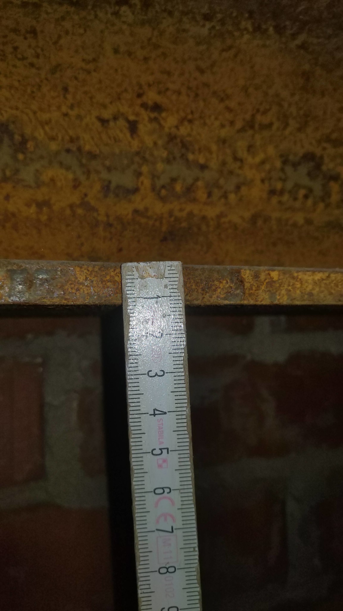
The I-beam is 120 wide and 125 high.
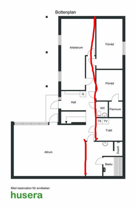
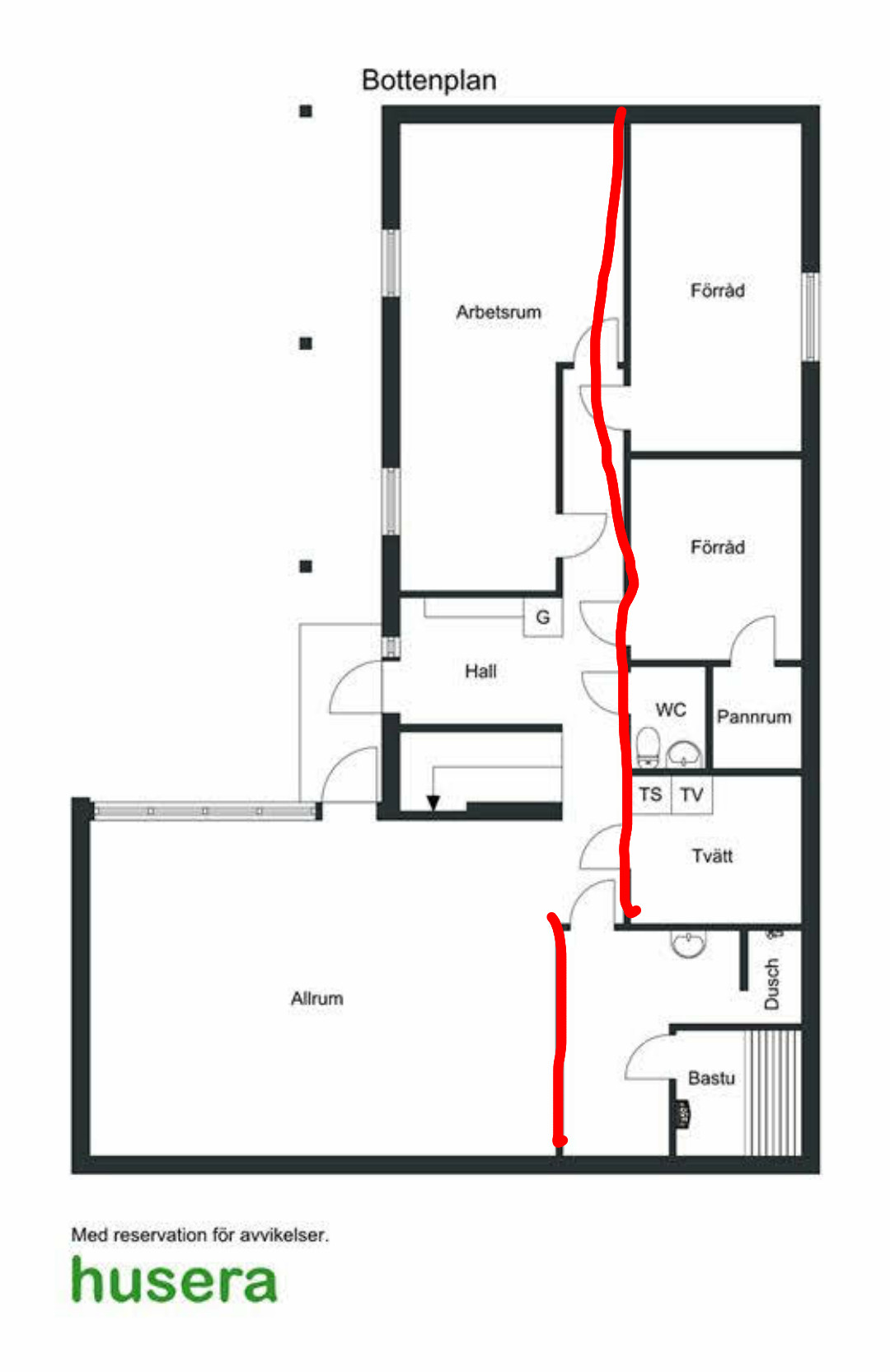
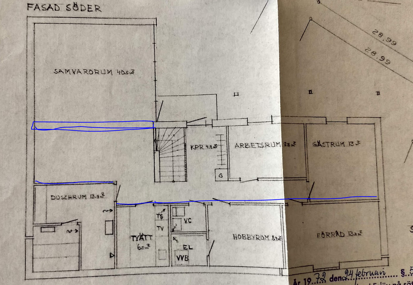
The beam sits by the wall marked in red in the image below. The wall is framed (single brick)
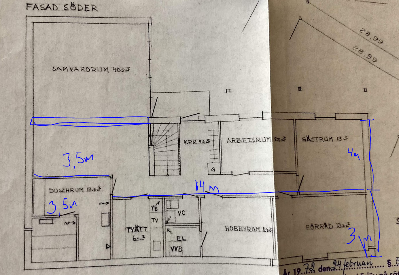
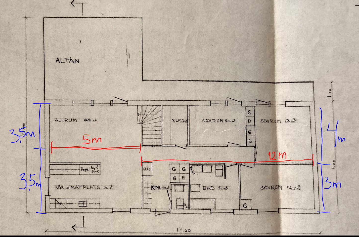
The span between the outer wall and the beam is 300cm on one side and 400 on the other side.
The beam measurements do not match any profile known to me. Have you really measured correctly? I think it seems proportionally higher than it is wide.
Wouldn't it be easier to replace the studs with standing square steel profiles with the same width as the beam? Standing on iron plates with felt or rubber sheeting against the concrete.
A HEB 120 is quite a strong beam. With a span of 4 meters, it can handle a distributed load of 6 kN per meter. Can you specify exactly where the beam is located and how long it is?
An HEB 120 is quite a strong beam. With a span of 4 meters, it can support a distributed load of 6 kN per meter. Can you specify exactly where the beam is located and how long it is?
Yep. See below.
Then we have a brick wall right next to the beam, so the beam doesn't take the entire load.
The standing posts that are to be replaced (the I-beam is not to be replaced) are 120x120, so perhaps the question is really what the compressive strength is for such a post. The I-beam has support with approximately 2 meters intervals – either a post or a masonry wall.
Vi vill skicka notiser för ämnen du bevakar och händelser som berör dig.