Then it was time for me to start a "Is this a load-bearing wall, which beam should I use" thread...
The conditions are:
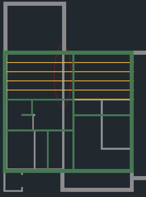
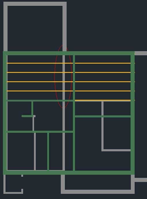
Total width of the house is 8.5m with a wall, which Skanska calls load-bearing, built with 95 mm studs instead of 70 that support a 45*225 floor joist. The distances from the outer wall to the load-bearing wall are 3.8m and 4.5m, respectively.
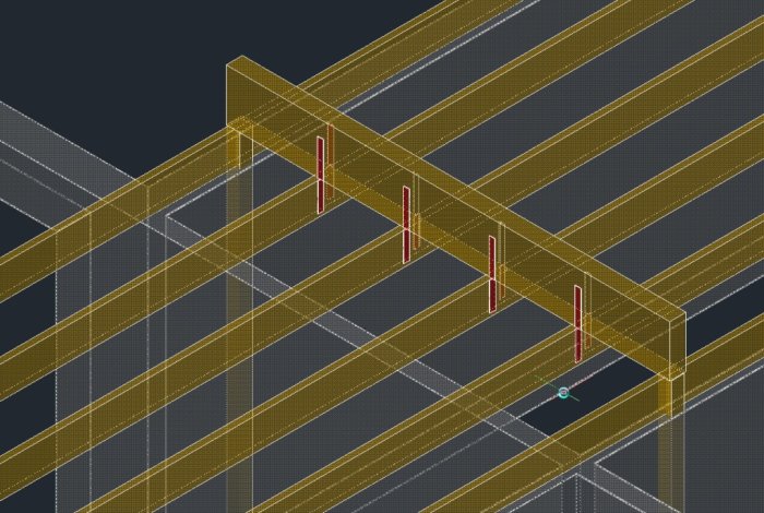
In the image below, gray is the ground floor, green is the upper floor, yellow is part of the floor structure. It is the wall circled in red that needs to be removed.
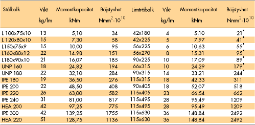
So far, there are no problems, Moelven suggests I should have an LT 115*315, which would give a deflection of 6 mm, 30 kN pillar load, Svensk Limträ suggests an LT 115*315 with 5 mm deflection, so it seems to be in the right ballpark. Then the question is whether I can use their calculations, our roof trusses are not in the same direction as the floor joist but across the joists.
But, I don’t want 315 mm down from the ceiling!! What I want to do is to recess the pillars into the walls so that the opening is maximal, about 3.2m, and also to recess the load-bearing beam into the ceiling so that it becomes a smooth ceiling in the whole room. Then the glulam beam is out, and it leans towards steel.
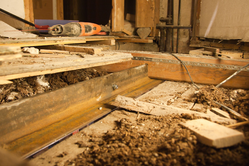
I found the image below on this forum,
which would then give an IPE 180 as an alternative or an IPE 200 so that I have both belt and braces.
HEA and HEB are not relevant, they are too wide.
So far, the theory, is this feasible?
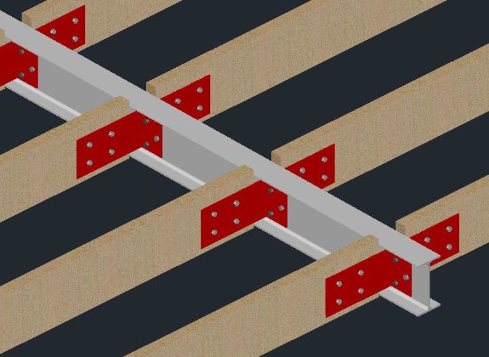
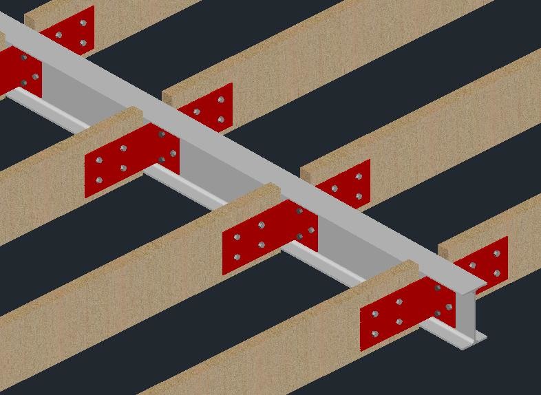
How is an I-beam recessed into the ceiling - I have searched online but haven’t found a direct solution. I mused around today when I was already drawing up the house, is it possible to make a solution like the image below?
The idea is then to cut the joists so that the IPE beam goes in between and bolt the joists with substantial metal angles to the IPE. Suitable pillars then in glulam or steel that are also bolted to the IPE. This will anyway prevent the IPE from falling or twisting, but is this how one could do it?
Those of you who are competent builders, feel free to judge/improve or come up with other suggestions...
One tip could be to bolt together two angle irons to create an upside-down T. Easy to recess, and you don't need to completely cut the beams. However, you might want to talk to a konstruktör as it's not a standard element.
Steel beam is what I would have chosen too.... but getting it completely into the floor structure will take some tinkering.... also remember that the support for the beam will have high pressure there... what kind of house foundation is it?
I would have chosen a steel beam as well... but getting it completely into the floor structure requires some fiddling... also remember that the support for the beam will have high pressure there... what is the house foundation?
Slab on grade. I would assume there will be some kind of steel plate as a base under the support.
It's clear that having a beam just under the floor structure would be simpler, but it would look much better to remove it completely, hence the brainstorming to see if it's possible with a reasonable amount of work.
Could be a way too. It's like a half IPE, so it becomes relatively rough anyway. The small piece that remains of the beam probably doesn't add much to the stability, maybe making handling easier. With 225 mm beams and IPE 200, you can do something similar and save a piece at the top.
Yes, there are no pulling forces to speak of in your case. But it makes handling easier to have proper storage. There will be many holes to drill for the bolts in the other variant.
That profile can never be compared with an IPE beam.
You would need to use two monsters (type 150x150x14mm) for angle iron to achieve the same moment of inertia as an IPE 200
What you should keep in mind when cutting the beams and inserting a hidden beam, is that the joist is no longer continuous. This means that the intermediate beams will bend more than when they were whole. Consider this as well if there is a bathroom on the upper floor in the area in question. Depending on how the light falls, it may also become visible that the ceiling goes in waves. A visible beam conceals the deflection better. Also, think beforehand if there might be installations such as ventilation or drainage currently located in the joist.
What you need to keep in mind when cutting the beams and installing a hidden beam is that the floor joist will no longer be continuous. This means that the intermediate beams will bend down more than when they were whole. You should also consider this, for example, if there is a bathroom on the upper floor in the affected area. Depending on how the light falls, it can also become visible that the ceiling goes in waves. A visible beam covers the deflection better. Also, think beforehand if there may be installations such as ventilation or drainage that are currently in the joist.
That was somewhat what I wanted to achieve (or prevent) by bolting the beams instead of just laying them on a recessed beam. The rooms above are bedrooms, so no heavy bathtubs or leveled floors to consider, nor ventilation or anything else, completely empty so far.
The plan is also to put noggings between the beams since I'll probably tear down the entire ceiling. It's gypsum planks that aren't even today and I want a completely smooth ceiling instead. As it stands, the floors creak or rather snap when someone walks upstairs, so I thought I'd see if it's possible to glue the chipboard panels from underneath and stabilize the construction. Skanska, who built the house in '81, hadn't accounted for nails in their budget. I noticed this when I renovated the bathroom on the upper floor, 7 m2 of non-glued chipboard flooring just nailed with 8 nails plus 2 pcs 4" nails that were all that held a 3 m long internal wall to the floor.
Yes, there isn't much in terms of tensile forces to speak of for your part. But it makes handling easier to have proper supports. There will be many holes to drill for the bolts in the other variant.
Many holes shouldn't be a major problem, I think. It just gets a price tag, so if I proceed with "my" model, I'd probably ask a local blacksmith to fix the holes, metal angles for support, and other things. As the construction looks in the picture, there are over 150 13mm holes (pull everything together with 10.9 M12?) in 5-8 mm steel, nothing I plan to drill myself or even succeed with precision. An alternative for some of the holes could just be to weld the angles directly onto the beam, but it might become a bit too unwieldy to handle.
Keep in mind that if you cut the floor structure, you change it from having three supports to only two. This can be a bit helpful to understand the difference in load-bearing capacity of your floor structure if you do this.
Time to revive this thread again. Nothing came of it last year, but this year it's intended to be used. A suitable project to start before summer is here, as house jobs will probably end up outside with roof and panel replacements.
First step, does anyone know of / can recommend a structural engineer, preferably in northern Stockholm / Täby, who can help with coming up with a suitable design for a recessed beam?
Not many tips on structural engineers unfortunately...
Anyway, continued drawing the house to submit the building notification when I realized I have a wall in the upper level 60 cm from the load-bearing wall below that needs to be removed. It’s a regular interior wall that can easily be demolished, insert a glulam beam resting on pillars from below within the walls, support the intermediate floor from above instead, and build the wall around the glulam beam instead. The only downside is an outlet needs to be moved up to 350-400 mm from the floor or replaced with a surface-mounted outlet.
Moelven's calculation says I'm fine with a 90*315, 105 mm support and 5 mm deflection. Could go up to 115*360, 83 mm support and 3 mm deflection. 90*90 or 115*115 in the posts. The pillar load ends up at 29 kN, concrete slab below cast in K250 (C25 today?), should work with a steel plate first to distribute the pressure.
I remember seeing twisted flat bars meant for attaching glulam beams at 90-degree angles to each other as in the picture above. Otherwise, it might work to use a threaded rod, M12 or similar, through both the glulam beam and floor joists, provided that the nuts on the top and underside are loaded with larger plates? Would be easier at least, and the nut height is taken care of by the slat panel.
The advantage of this option, no need to cut the floor joists, glulam is easier to handle compared to steel beams and I would think it’s much easier to demolish and build up 3 meters of interior wall compared to propping up half the house, cutting floor joists, and putting everything back together...
Now I just need a structural engineer to verify this option. Moelven claims it works if it’s under...
Moelven said:
When purchasing glulam manufactured by Moelven Töreboda AB, it is guaranteed that this calculation provides the required dimension according to the applicable standard, BFS 2011:10 EKS 8