I am renovating quite a bit in the house and have encountered this beam which, in my eyes, undeniably looks load-bearing. It consists of 2 pieces 145x45.
In the first picture, you can see the beam.
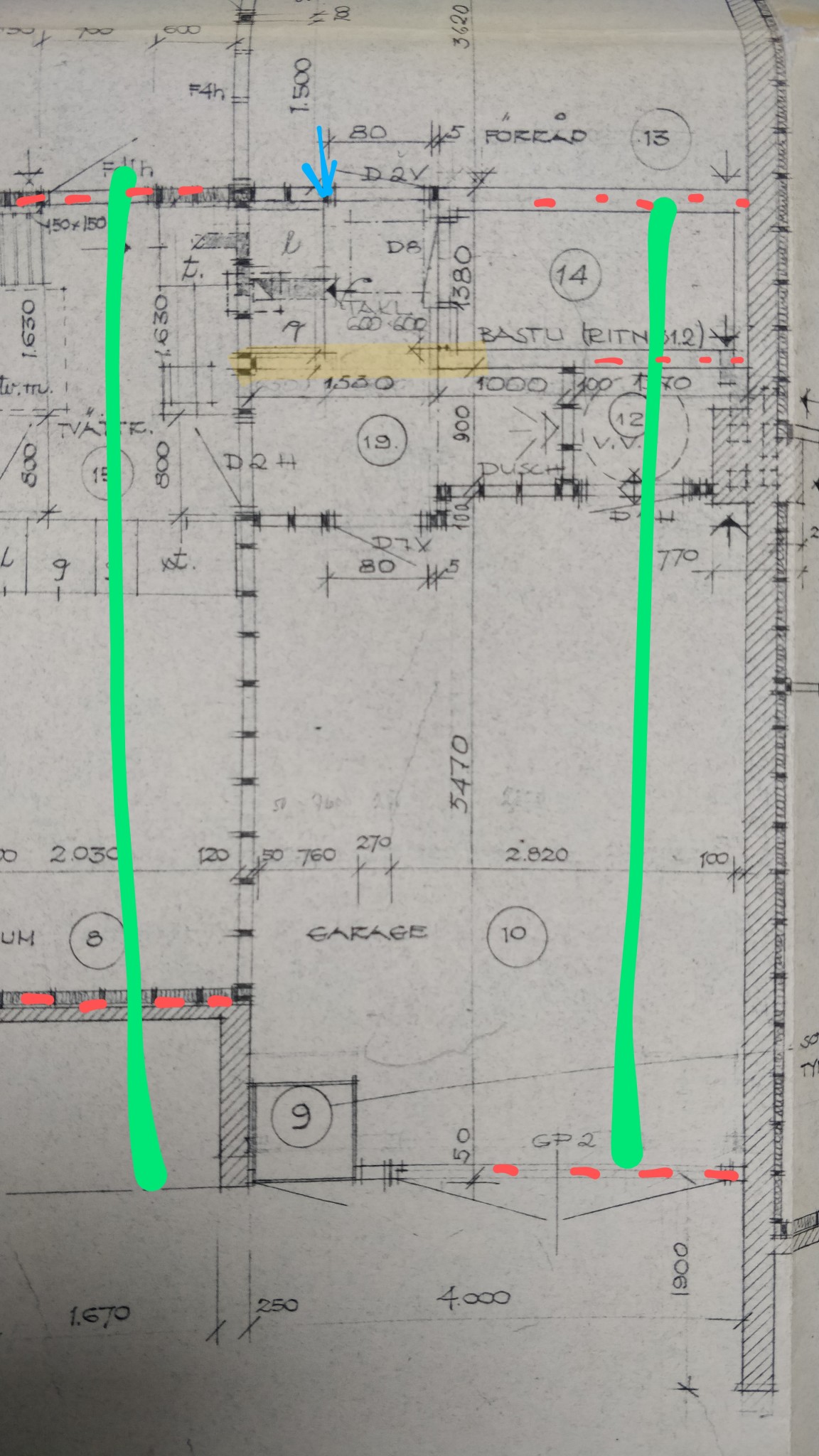
In the second picture, the building plan from -66.
Blue arrow shows where the first picture was taken from. Yellow marking shows where the mentioned beam is located. Green lines represent rafters. Red extending lines represent load-bearing parts.
One idea I have is that the rafters were built for the distance between load-bearing walls according to the left rafter marking. To get the same distance over the garage where there is no roof overhang, the mentioned beam was placed where it is? As far as I can see, the rafters do not differ.
The reason I'm asking is that I want to replace the current minimal attic hatch with a proper foldable attic ladder. Then the beam is in the way.
In the long run, the entire space will be removed and become part of the garage. I could then take the opportunity to set up a couple of glulam beams crosswise.
1 The report is too limited. You always want to see the entire floor plan.
2 Can you take photos of the trusses over the garage and residential area, respectively?
Click here to reply
Vi vill skicka notiser för ämnen du bevakar och händelser som berör dig.