Recently bought a house and am in the midst of renovation plans but have now hit a snag with a floor plan change that has proven more complicated than we thought.
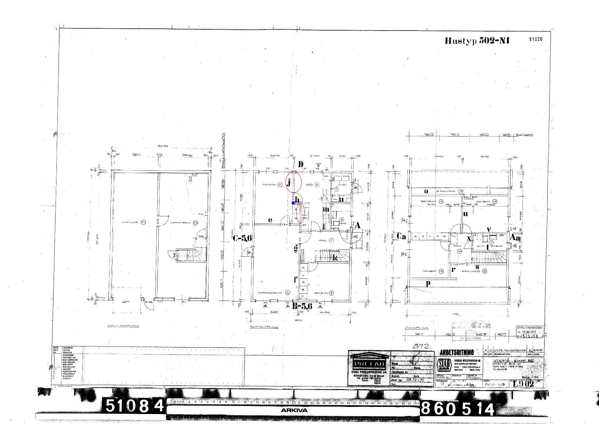
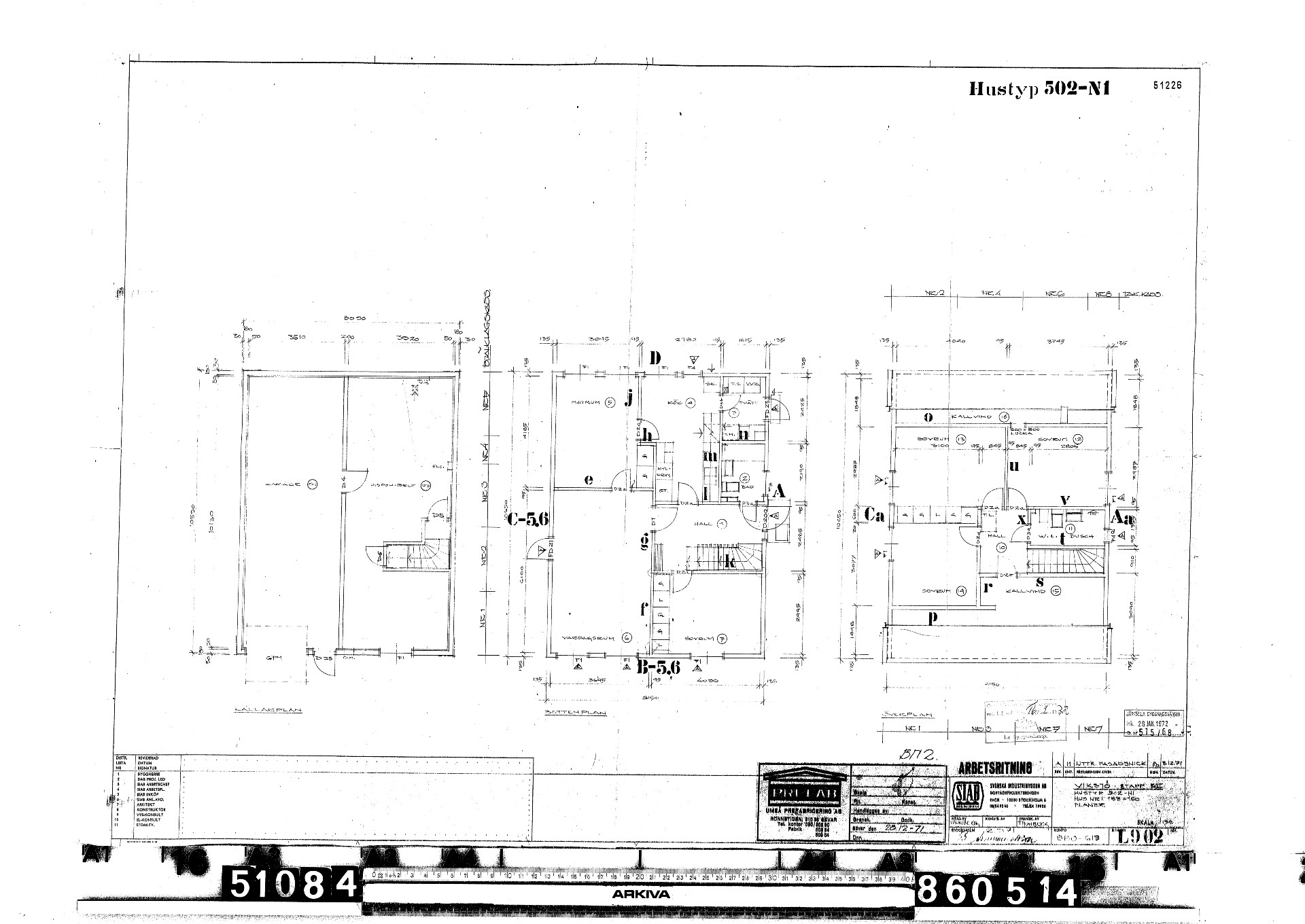
The plan is to completely open up between the kitchen and dining room, the catch is that it's not one but rather two load-bearing walls that need to be addressed. We also plan to demolish non-load-bearing wall "e".
Premises;
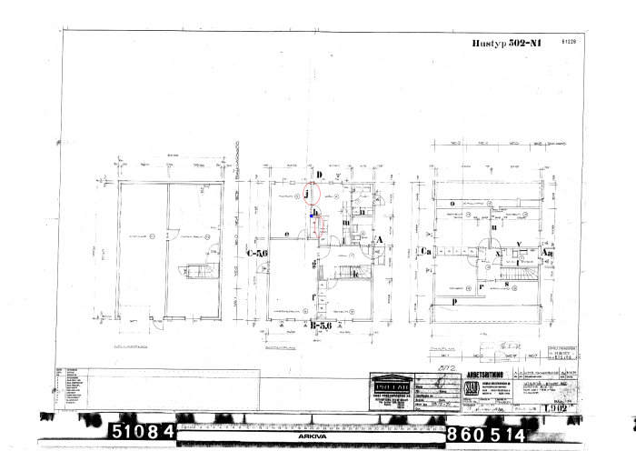
- Load-bearing partition walls on the entrance level are "f", "g", and "j".
- Wall "j" was previously demolished by the former owner and replaced with a beam. The blue circle on the picture marks the location of the pillar.
- Wall "g" is the longest load-bearing wall extending from the living room/hall into the kitchen, connecting to load-bearing wall "j" through non-load-bearing wall "h".
- To fully open up between the kitchen and dining room, the "kitchen part" of wall "g" must be demolished since wall "j" has already been removed previously. The pillar currently supporting the "j" beam (marked in blue) will also need to be moved to open completely.
So the question is; since it's not a single load-bearing wall in a straight line but two load-bearing walls with a displacement between them, where one also forms part of a longer load-bearing wall ("g"), how do you manage the support beam?
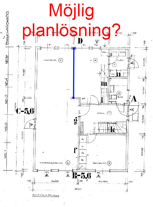
Is it possible to replace the existing "j" beam with a significantly longer beam (see picture "possible solution") that would support the entire opening and replace both load-bearing walls even though the two original load-bearing walls are not aligned with each other?
I have sent all the drawings to a structural engineer and am awaiting a quote but thought I would ask here and hope someone has some ideas. I know that at least one neighbor with an identical house has made this type of change and have heard that it required a special construction element ordered from Umeå (?), also awaiting contact with this neighbor. Is it really that complicated or is there a simple solution?
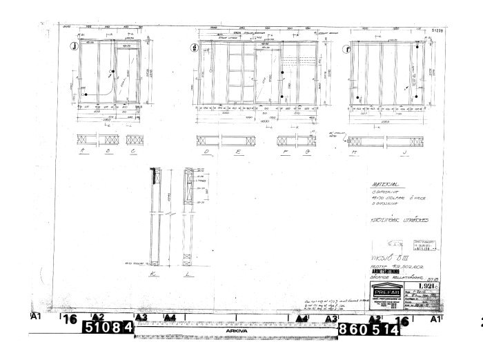
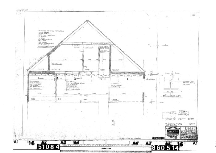
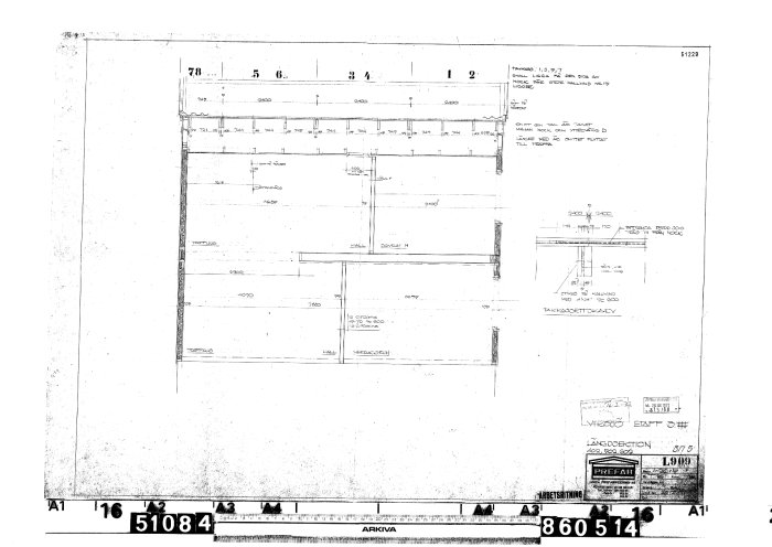
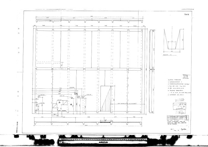
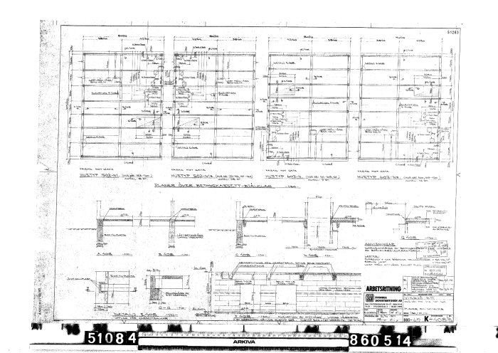
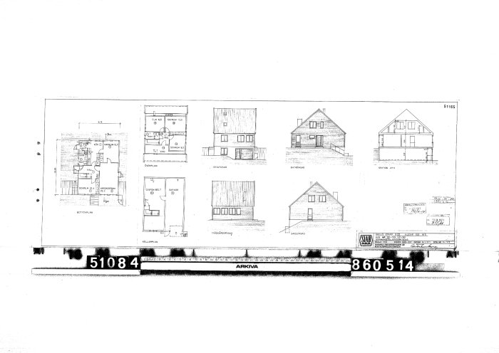
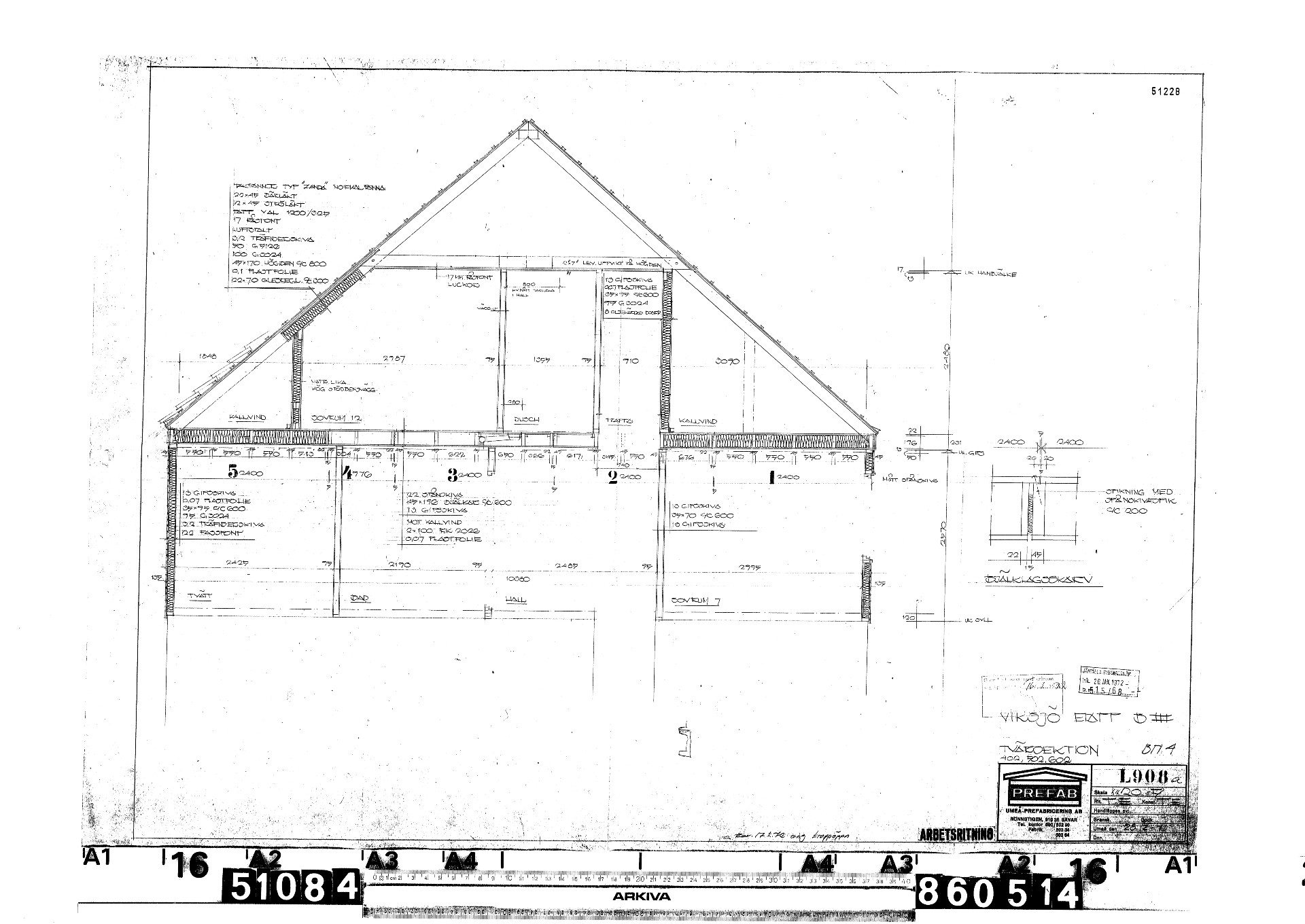
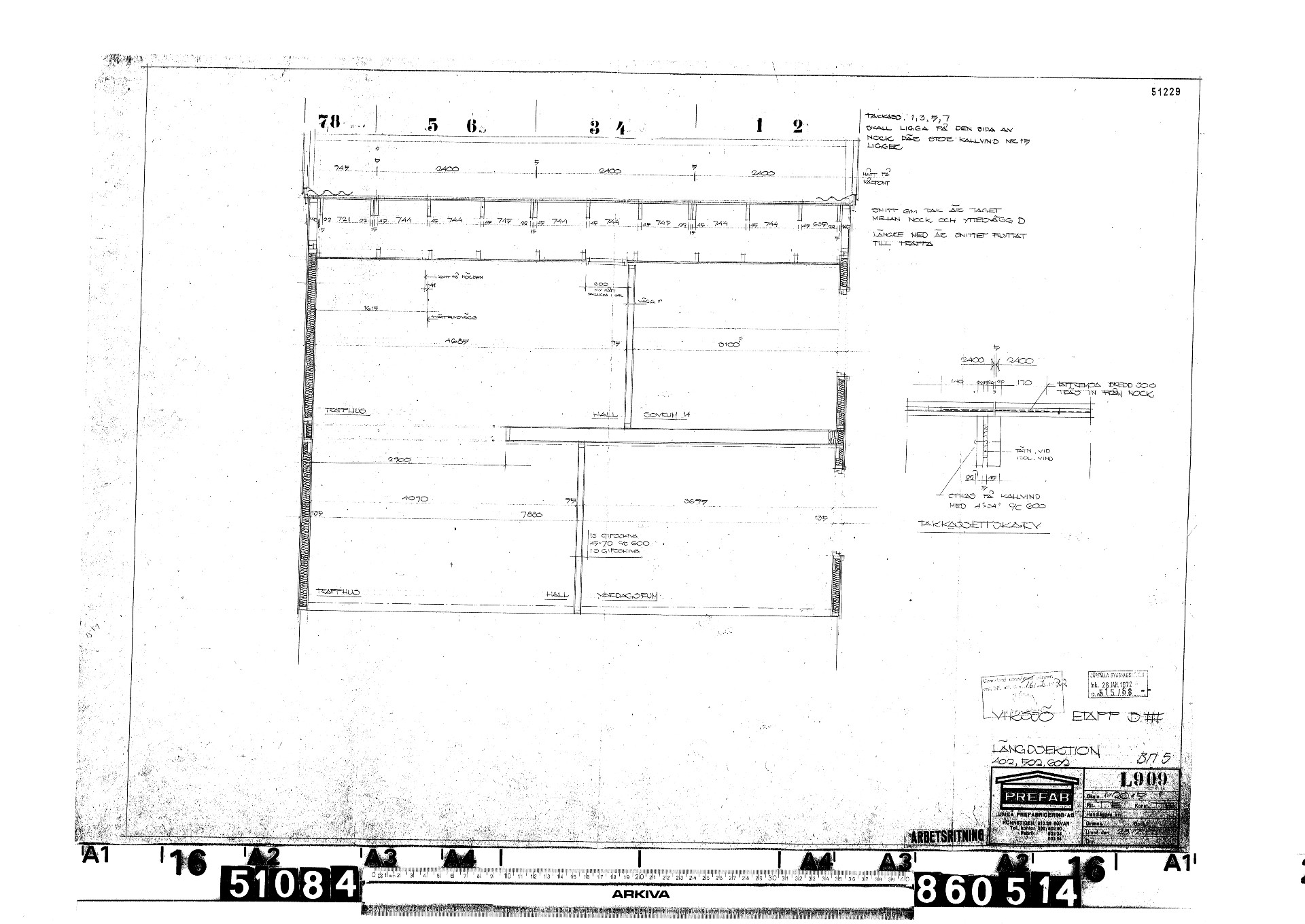
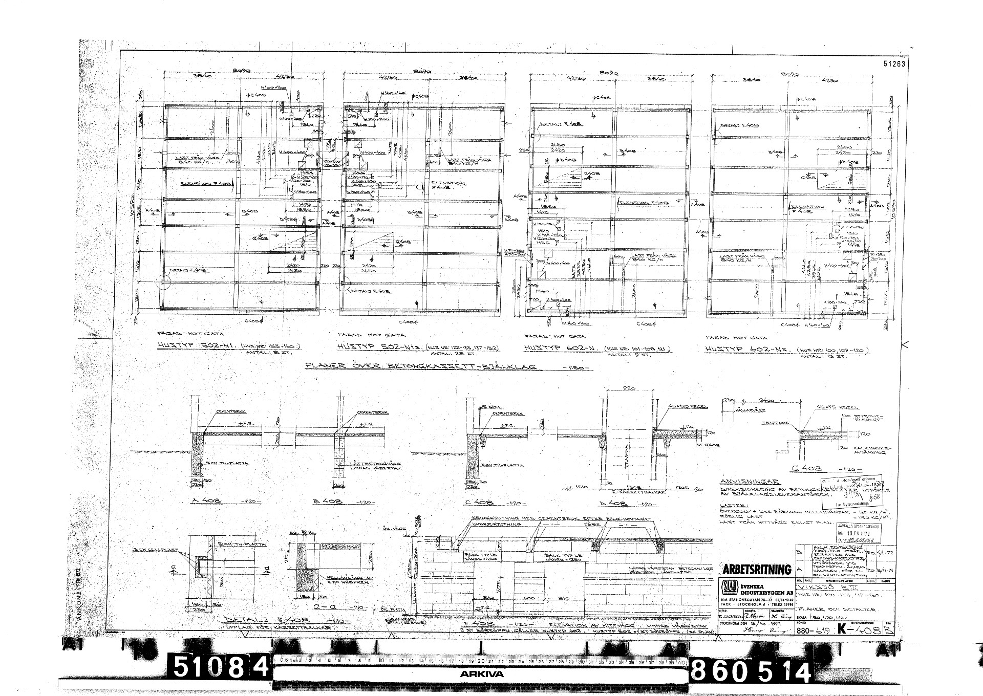
Attached are drawings/pictures of the floor plan, wall schedule, load-bearing partition walls, possible solution?, floor structure, etc.
Spontaneously, I think walls e and l should be load-bearing?
Then maybe also f, g, j, and h?
I understand the thought, but according to the original drawings, f, g, and j are load-bearing partitions. I can also spontaneously think that e+l should be load-bearing considering they run 90 degrees against the roof trusses, but among the original drawings, I only find info that f, g, and j should be load-bearing partitions.
I will see if I can reduce the size of the image files to make them easier to open.
A complicated structural framework that is not entirely straightforward to analyze. The floor slab against the basement consists of concrete cassettes that run parallel to the roof ridge. The floor slab between the ground floor and the upper floor is a conventional timber joist floor, with the joists also running parallel to the ridge. Finally, roof trusses run perpendicular to the ridge. This means that wall "e" is also partially load-bearing. Additionally, it has an important stabilizing function. If wall "j" is to be opened up more, it might be necessary to scrap the old load distribution. The column is not ideally located because it is offset in relation to the basement wall. At the same time, the window layout makes it difficult to move the load distribution sideways. As for wall "e," I believe it cannot be completely removed, and you will have to settle for a somewhat larger opening. The placement of the beam and column at wall "j" should preferably be decided in consultation with a structural engineer who can assess the conditions on-site.
A complicated building frame that is not entirely easy to analyze. The floor structure against the basement consists of concrete cassettes that lie parallel to the roof ridge. The floor structure between the ground floor and the upper floor is a conventional wooden joist floor with beams that also run parallel to the ridge. Finally, the framework trusses lie perpendicular to the ridge. This means that wall "e" is also partially load-bearing. Additionally, it has an important stabilizing function. If wall "j" is to be opened up more, the old beam should probably be scrapped. The pillar has no ideal placement since it is offset in relation to the wall in the basement. At the same time, the window arrangement makes it difficult to move the beam laterally. Regarding wall "e", I believe you cannot remove it entirely and will have to settle for a slightly larger opening. The placement of the beam and pillar at wall "j" should preferably be determined in consultation with a structural engineer who can see the conditions on site.
So something has been learned from slavishly reading your posts here on the forum
Click here to reply
Vi vill skicka notiser för ämnen du bevakar och händelser som berör dig.






Violina said: