3,134 views ·
14 replies
3k views
14 replies
Load-bearing for larger opening in gable
Hello,
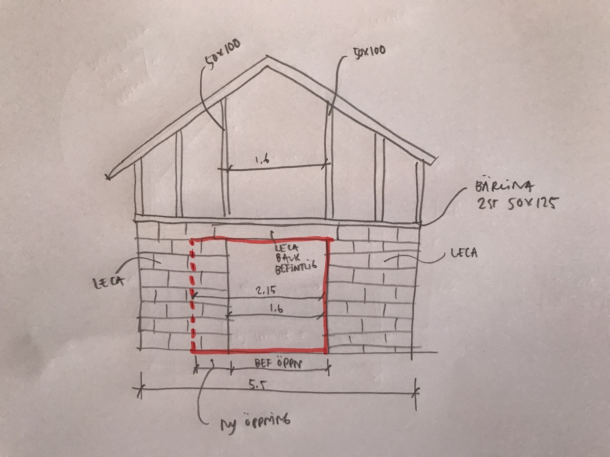
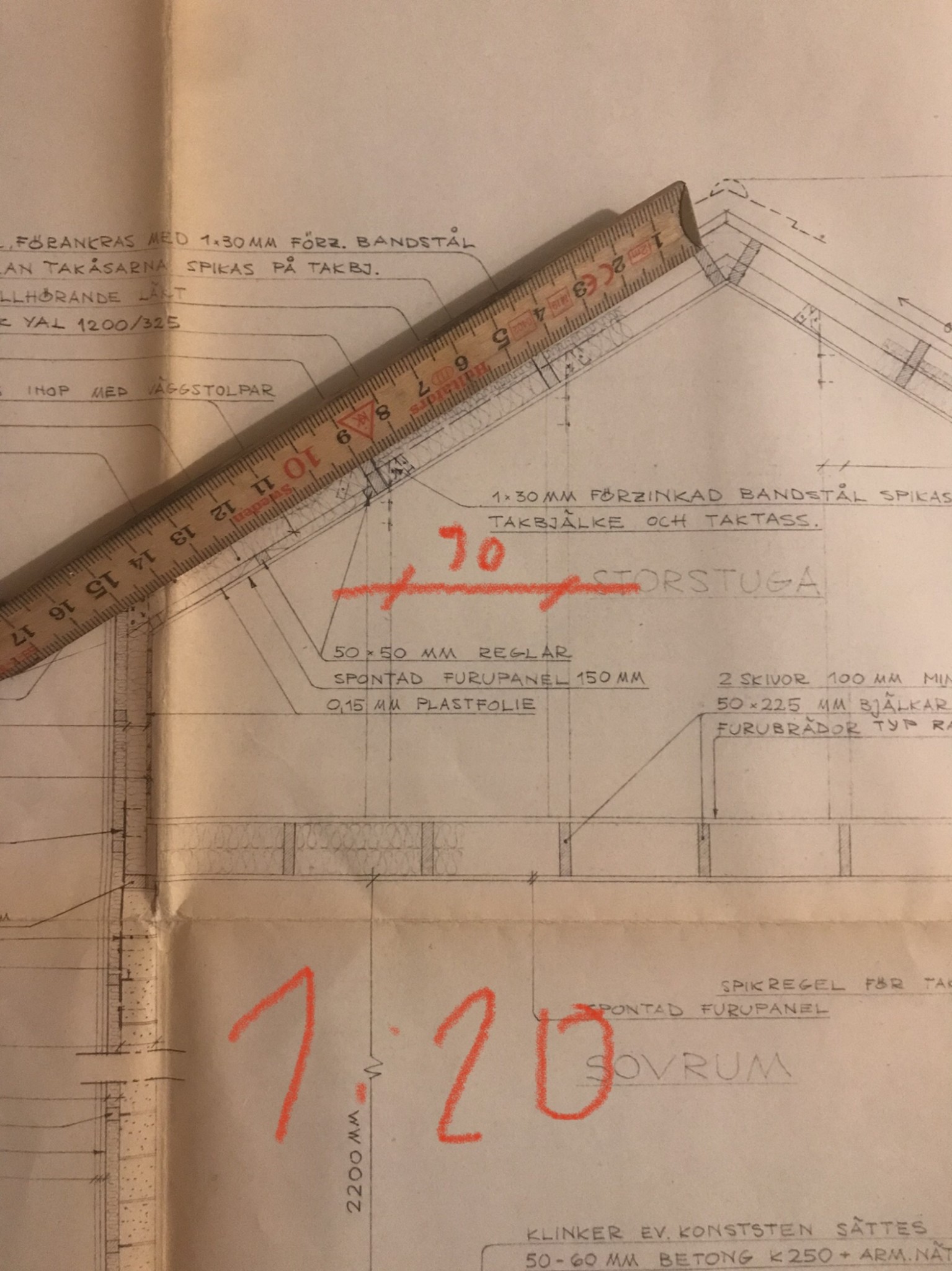
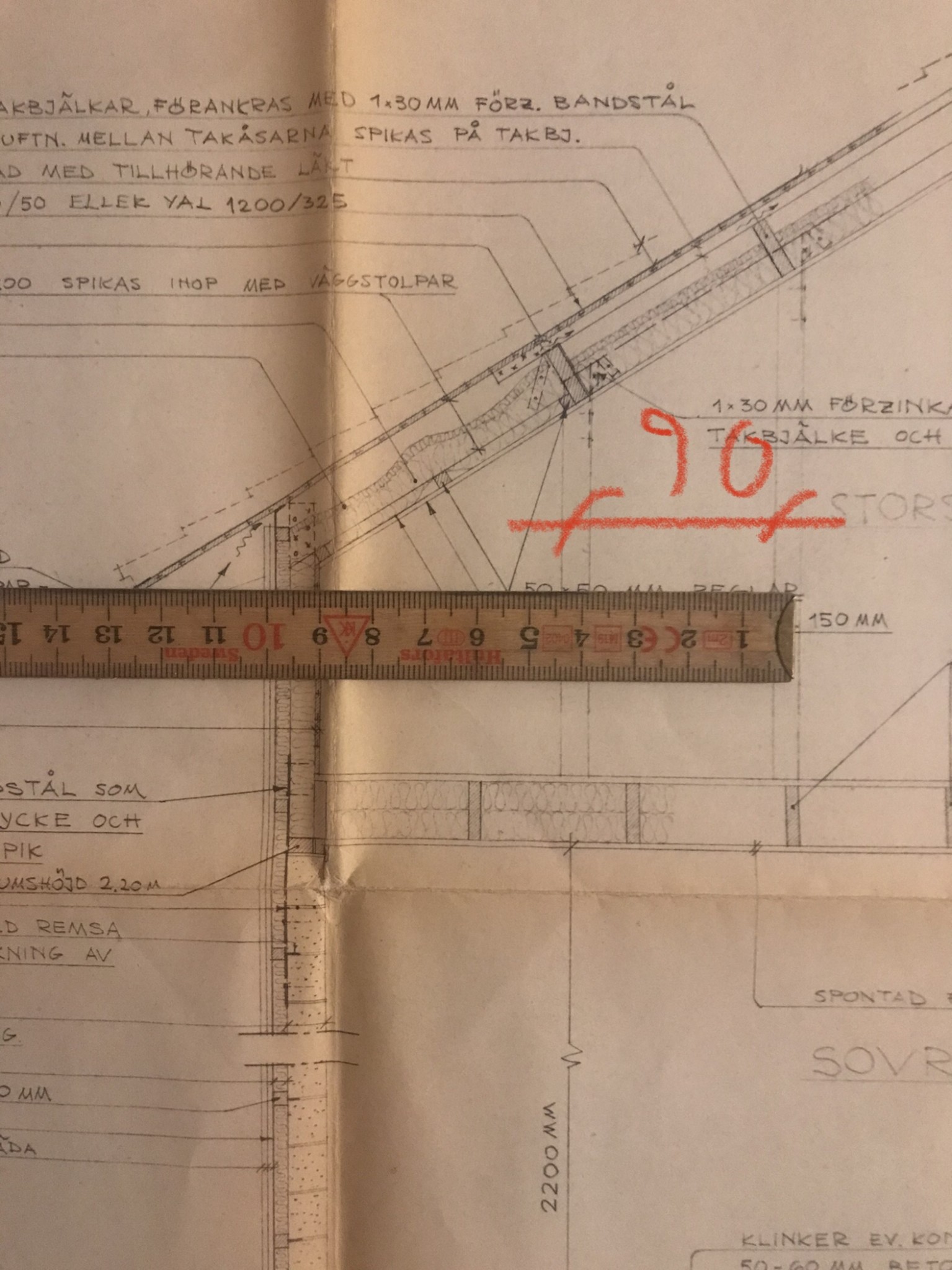
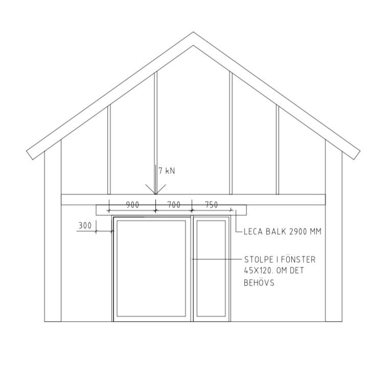
I have a low 1.5-story house with Leca on the first floor and a wood frame on the upper half. On the lower floor, there is currently an opening of 1.6 m in the gable where a double door is installed. I want to increase this opening to about 2.15 m in one direction. On the upper part (wood frame), the same 1.6 m opening is directly above my existing opening. On the sides of this upper opening, there are two studs, which means that when I want to increase my opening width below to the new 2.15 m, one of the studs ends up on the new larger opening. How much load are we talking about? Is it enough to just place a longer Leca beam and that it can handle the load, or do I need steel? The height I have available for the load-bearing beam is 200 mm, and the house is located in Halland.
Thanks in advance!

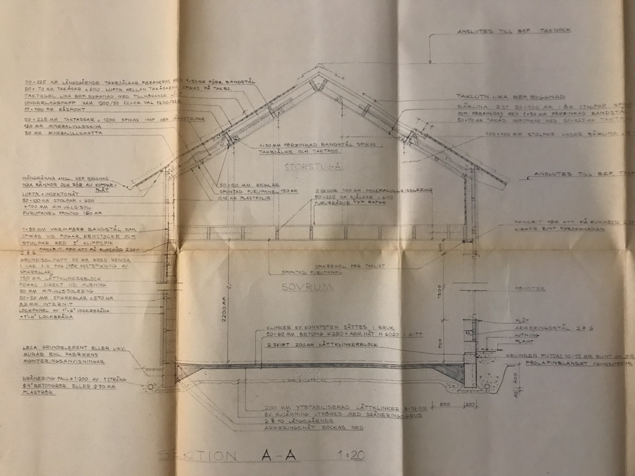
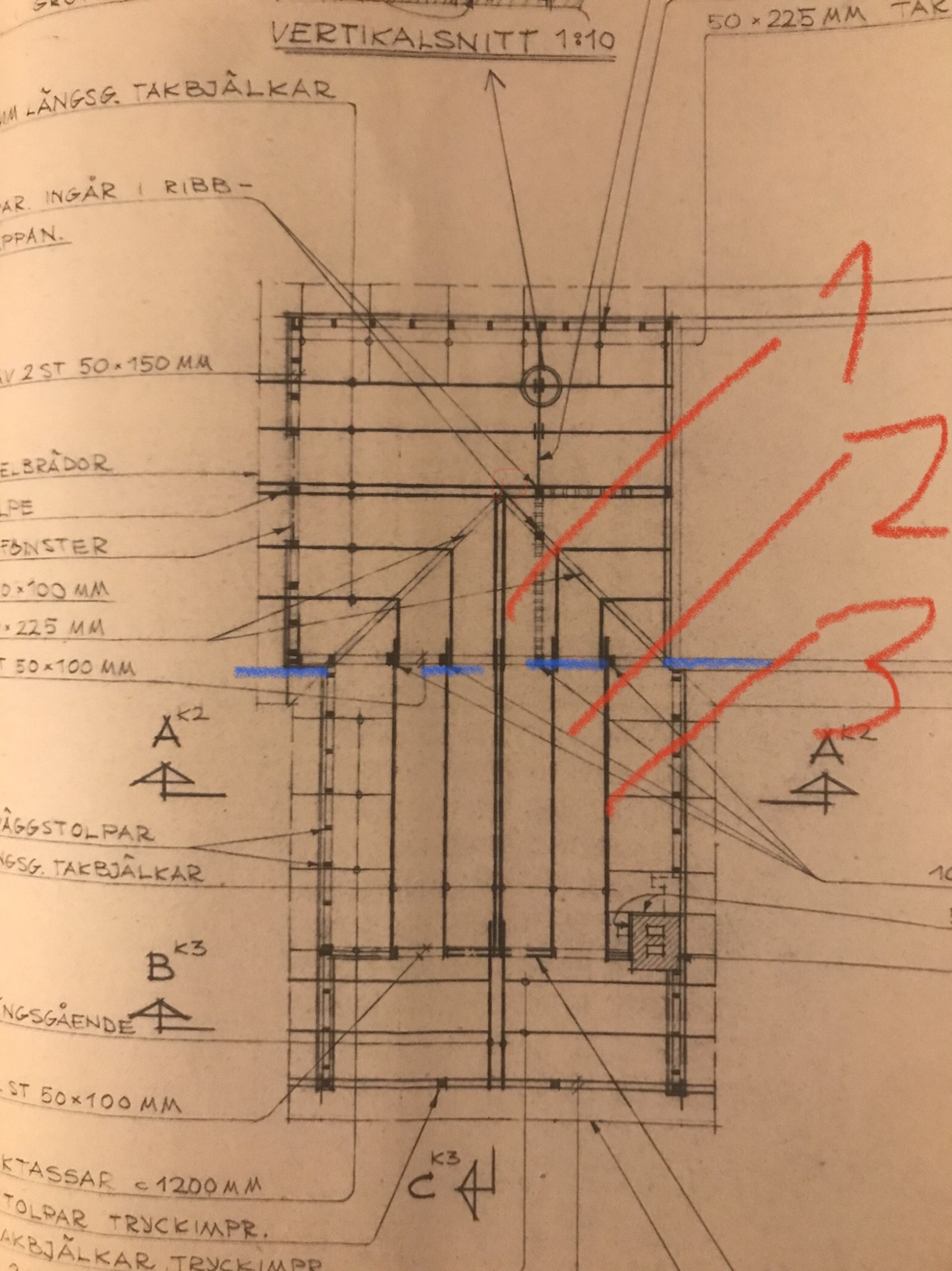
More information is needed to be able to calculate it: Roof pitch and c/c distance between the rafters. I assume that there are regular rafters between the gables. Also, aren't there more vertical studs than the 6 you have drawn?
Thanks for the response!J justusandersson said:
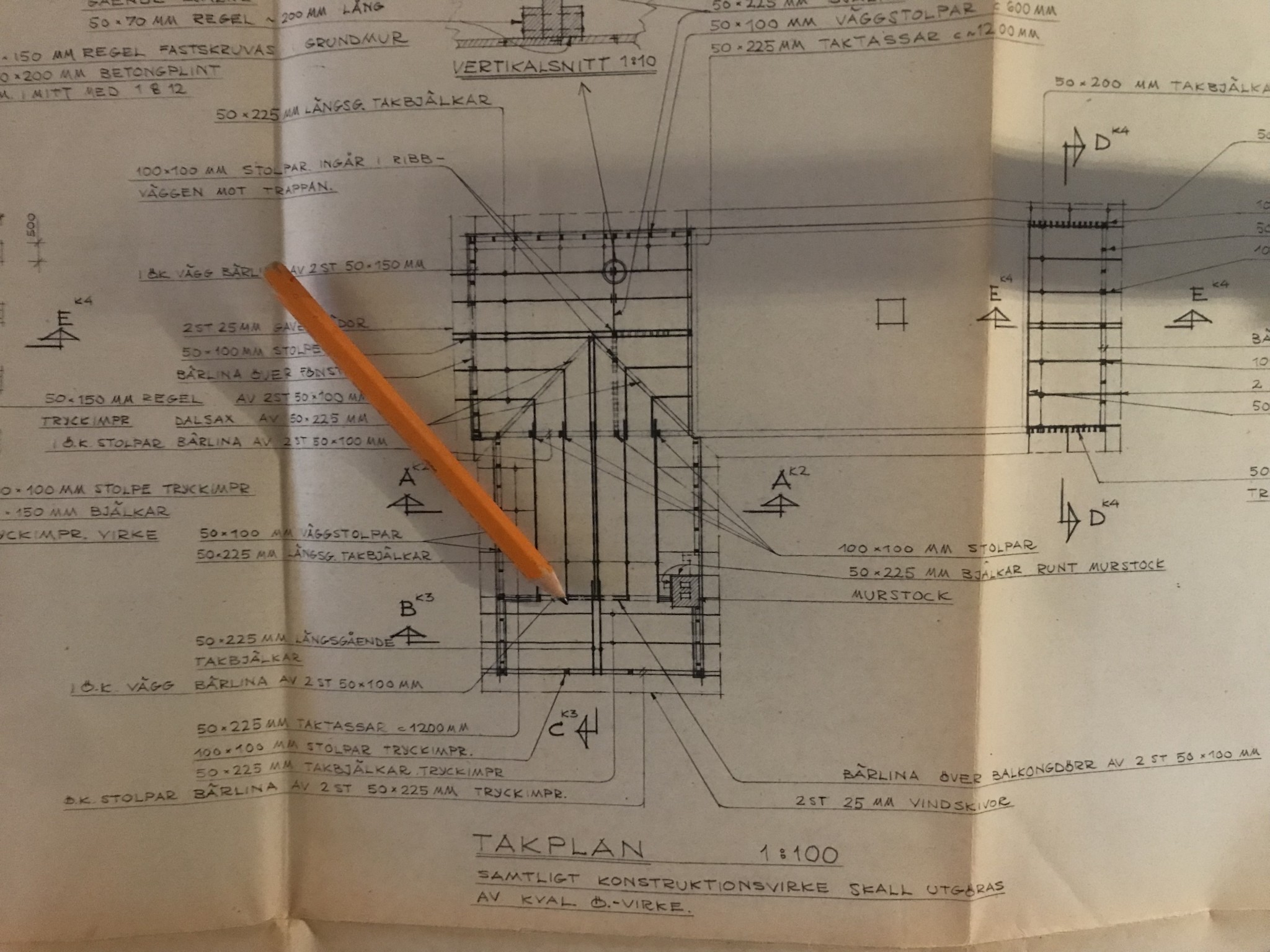
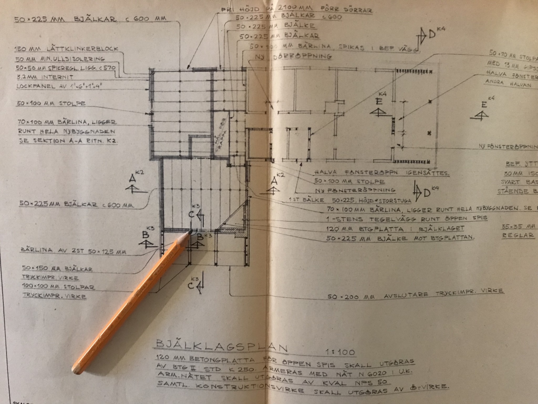
The roof angle is 30 degrees. The rafters aren't exactly there, rather beams run in the opposite direction than typical rafters. Please see the drawings I attached, which might clarify. The pen shows the current opening.
Regarding the vertical studs, there aren't more than what I've drawn...
Original solution even if it complicates the whole thing. Then I need to know the length of the ridges and their mutual distance.
I get the point load to roughly around 7 kN. Lecabalkar is not an unambiguous term. They have different dimensions, and the load-bearing capacity per meter also depends on the span. A sturdier model should work. At least you have something to start with.
Thank you so much for this!
For me, it doesn't really matter if it's leca-balk, steel beam, or wood. I'm thinking that I want the most economical option that can handle the load and a maximum height of 200 mm. Do you have any recommendation there?
For me, it doesn't really matter if it's leca-balk, steel beam, or wood. I'm thinking that I want the most economical option that can handle the load and a maximum height of 200 mm. Do you have any recommendation there?
Hello again,
How do you assess this situation? Can it withstand a point load of 7 k/N? The product sheet specifies the load as max 5 kN/m for a lecabalk of 2900 mm and 10 kN/m for a lecabalk of 2400 mm.
Thanks in advance : )
How do you assess this situation? Can it withstand a point load of 7 k/N? The product sheet specifies the load as max 5 kN/m for a lecabalk of 2900 mm and 10 kN/m for a lecabalk of 2400 mm.
Thanks in advance : )
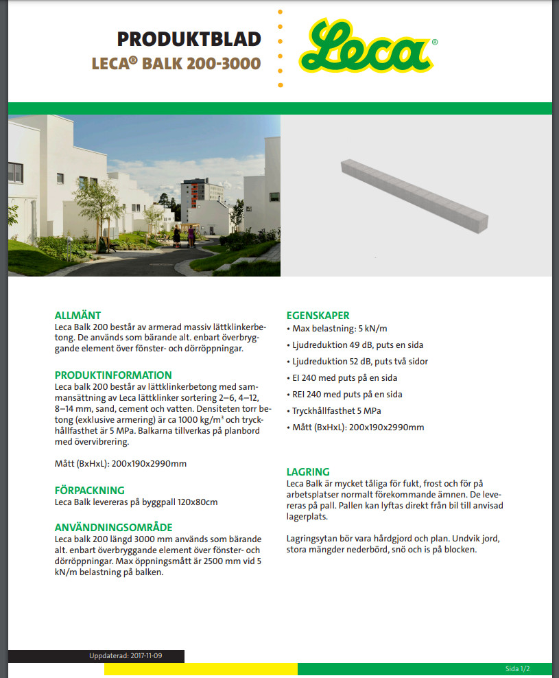
In general, I believe that Lecabalkar work best with distributed loads. A 2400 mm beam that can handle 10 kN/m is probably sufficient, but it's a bit bothersome that one cannot calculate it more precisely. Steel beams of HEA type become very small in relation to the size of the Lecablocks. There doesn't seem to be any truly optimal solution.
S_Moln said:
Thank you again for the response
It's a bit short, the beam that is 2400 mm. And the longer one, 2900 mm, can handle less load. Did you see the PDF sketch? I was wondering if it would help if I put a stud in the window section, between the door and the fixed window? To be able to use the 2900 mm beam.
Or should I rather choose two glulam beams 45x180 instead of leca beam?
Thank you again for the response
It's a bit short, the beam that is 2400 mm. And the longer one, 2900 mm, can handle less load. Did you see the PDF sketch? I was wondering if it would help if I put a stud in the window section, between the door and the fixed window? To be able to use the 2900 mm beam.
Or should I rather choose two glulam beams 45x180 instead of leca-
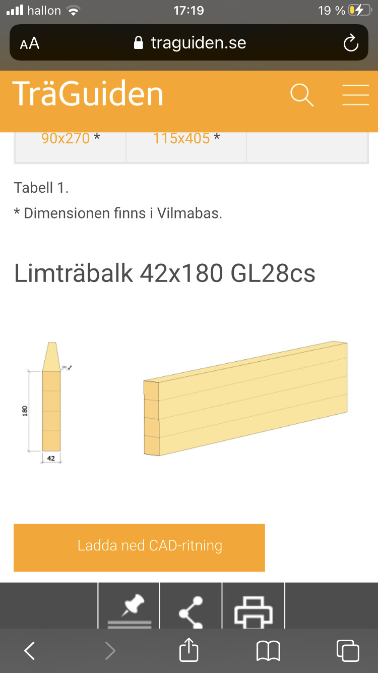
Since it is a window section, there are reasons to limit the deflection additionally. If you choose a 90x180 glulam beam, you have good margins. It is better to increase the width than to double the glulam.
Yes.
Click here to reply