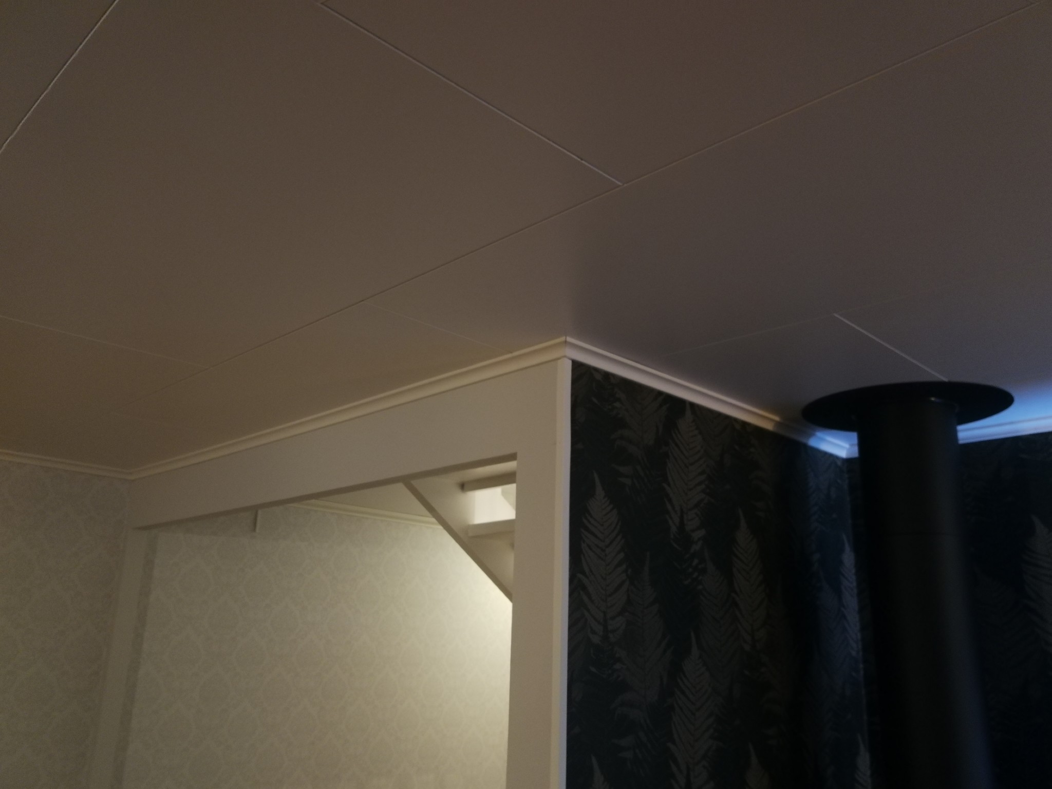
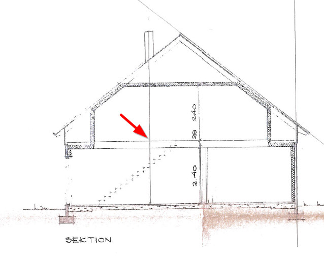
Hey! We had a stove installation today in our 1.5-story house. 70s, concrete slab. The stove is on the ground floor, and during the ceiling penetration, a bridging joist was cut to get the correct air clearance for the chimney pipe. The pipe goes straight up and free from the roof trusses without issue, but this joist needed to be sacrificed.
According to the installer, it shouldn't be a problem since it's not structural, but initially, it seemed like it might require a trimmer beam. At least according to the first guy who came to measure. A bit unsure if he meant the joists connected to the roof trusses and not the ones between them, like this one.
Given the slightly different opinions - is there any issue with the bridging joist being cut in this manner? Does it serve any function other than leveling the floor on the upper floor? Is "bridging joist" even the correct term? I'm planning to replace the floor upstairs soon, so I could access it from the other side of the pipe if necessary.
Assuming that by "mellanbjälke" you mean the floor joists that run parallel to the rafters, but in between them to achieve 60 cm spacing in the intermediate floor?
Yes, exactly, parallel to and between the beams that are attached to the roof trusses. The question is how I, as an amateur, can get a little more informed here without being an engineer? As mentioned, I can open the floor from the other side and take some action from the side, but I don't know how to do it correctly. I wasn't asked before the beam was raised either, so it feels a bit disappointing!
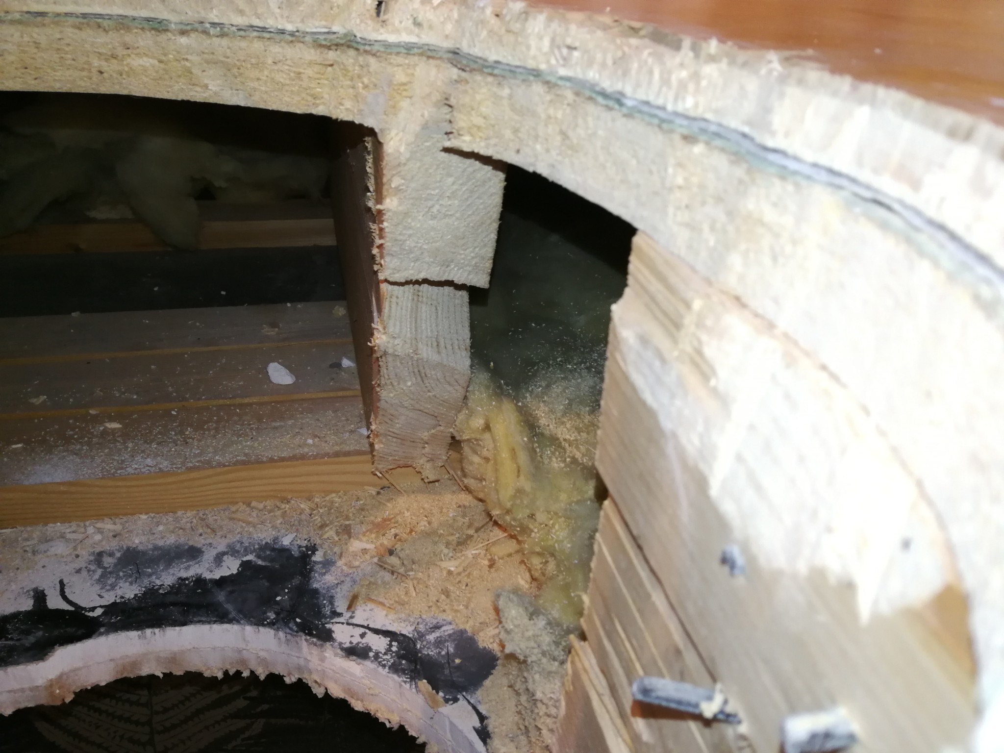
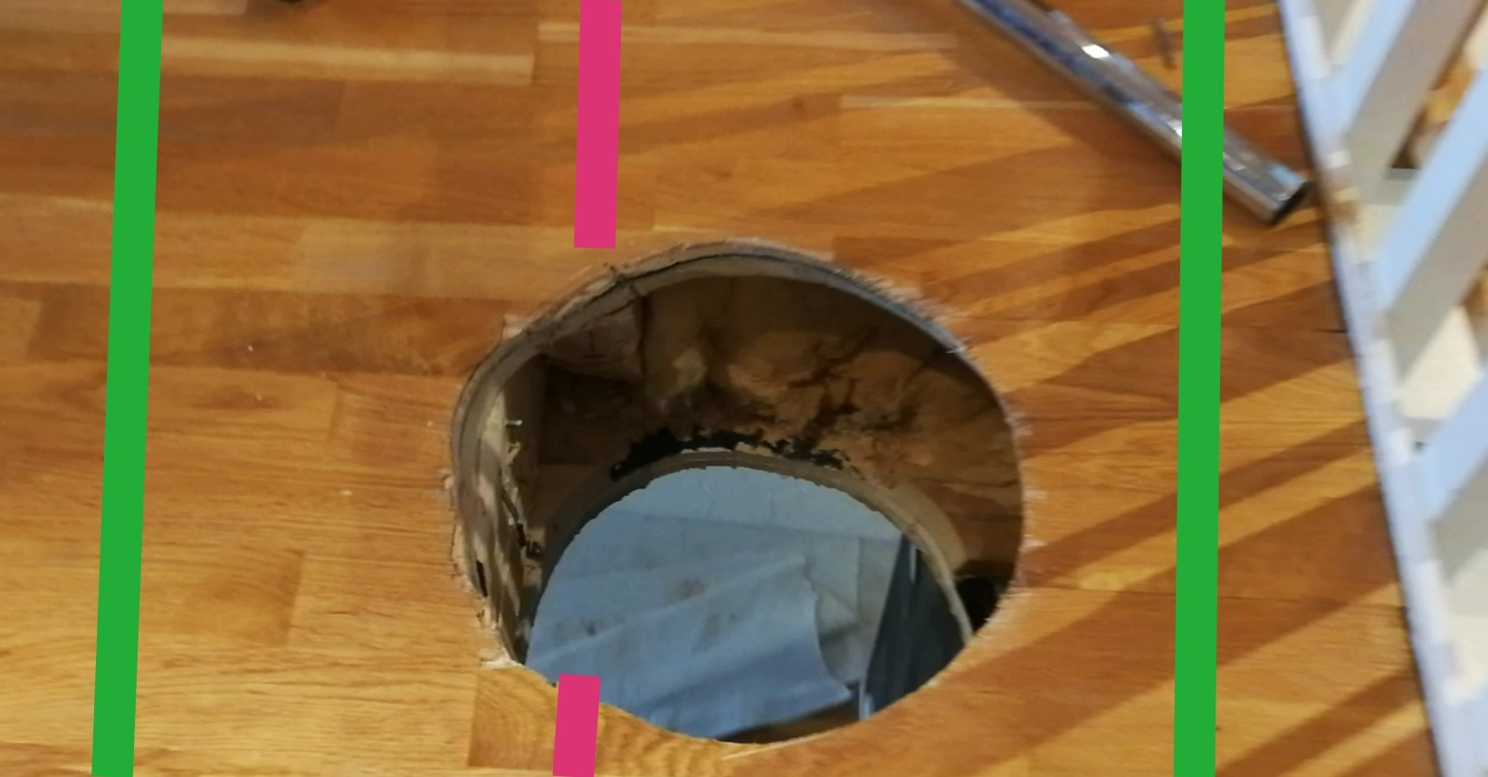
It looks like they needed to "hollow out" rather than cut all the way, as they didn't really need to remove the entire thickness. But off it is.
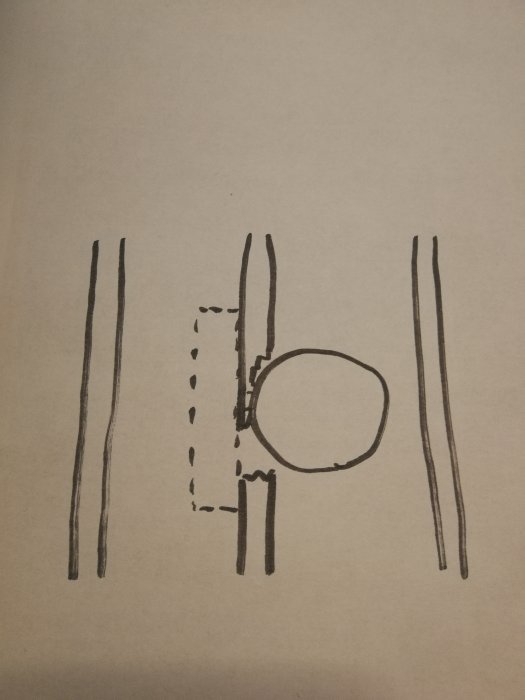
Because of this, it should be possible to place a beam on the side according to the sketch (dashed) below, without getting too close to the pipe. The question is, what good does it do?
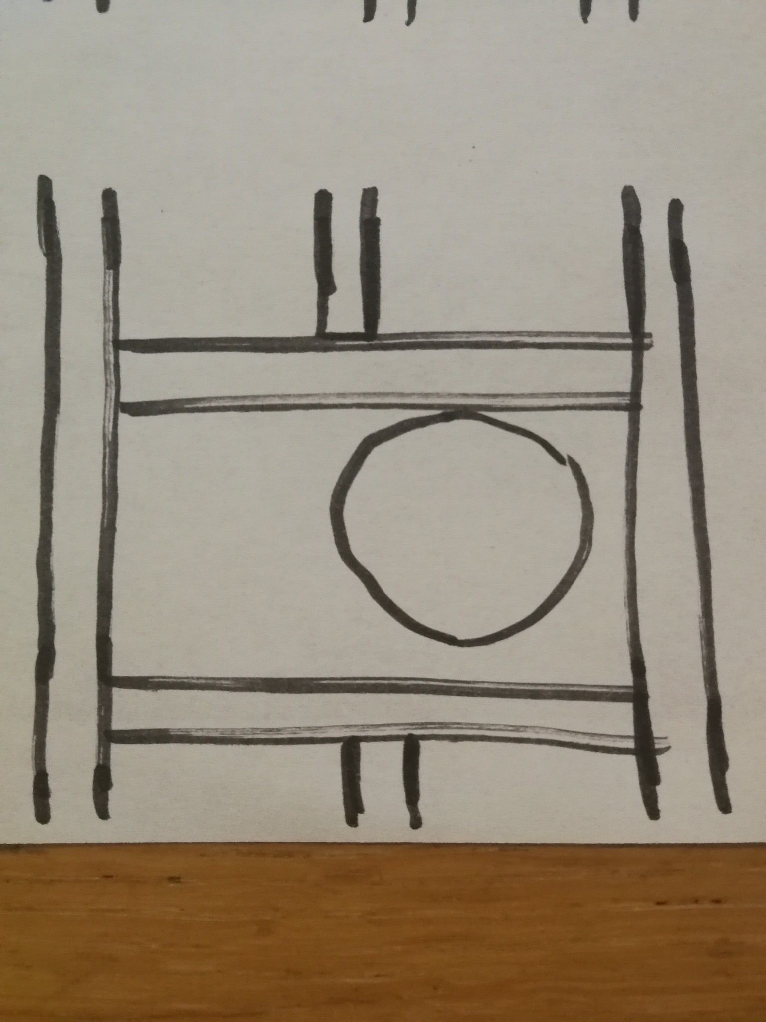
The alternative seems to be according to sketch 2, but as I mentioned, I can't calculate the needs myself. I was thinking of seeing what the stove company says this week.
The best solution would be to place a beam of similar thickness next to the cut one, extending from support to support, i.e., from the outer wall to the load-bearing central wall. Naturally, this would be a significant intervention, making it something you would ideally like to avoid for practical reasons. Alternatively, perhaps it would suffice to splice in a piece according to your first sketch, but it must be significantly longer. The longer, the better, and ideally, as I mentioned above, from support to support. I can't say what is sufficiently good/long. I would guess that a 120 cm overlap on each side, screwed and glued to the old beam, might suffice, but I don't dare to advise.
Your option 2, where the beam is supported by the rafters, is what is usually done, so presumably the rafters should be able to handle the extra load, but again, it depends... You can't always assume such margins exist. Also, there seems to be a staircase somewhere in the vicinity. This means the flooring is staggered there as well. If it is 180 cm or further away, it probably doesn't matter though.
I can't calculate this, but there are one or two people here on the forum who might be able to, but they would need more information. Primarily drawings of the rafters, and probably the floor plans both upstairs and downstairs. Preferably construction drawings with all the necessary information on dimensions, etc.
Thank you very much. Given all the variables and variants here, it's even more interesting that the company chose to simply cut off the intermediate beam. But the foundation is that intermediate beams also have some structural function beyond flooring, right? Many thanks.
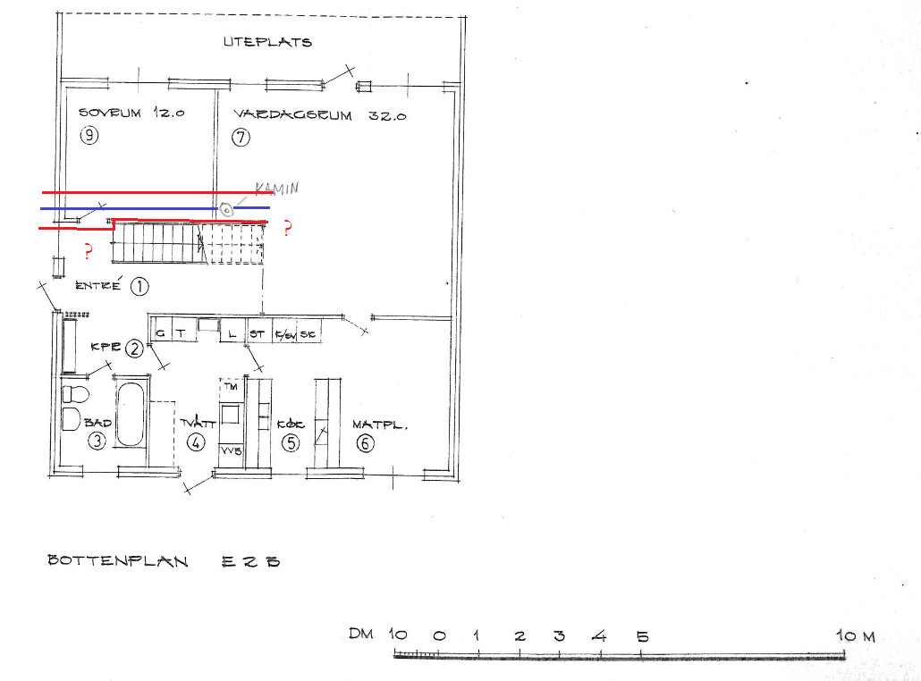
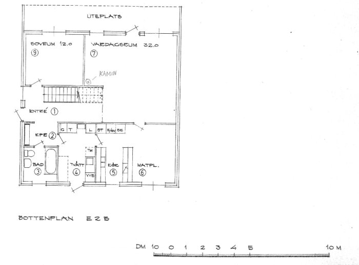
Regarding the floor plan/heart wall, the ground floor looks like this. The dashed line at the end of the stairs corresponds to a thicker beam that goes slightly below the ceiling downstairs, so I assume that it's load-bearing. However, it only spans that opening. There's no continuous heart wall.
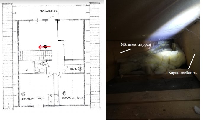
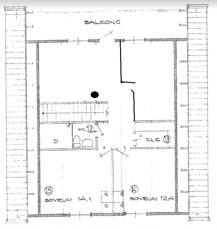
The upper floor roughly:
Unfortunately, I haven't seen any sketch of the joists.
But the basic idea is that even intermediary beams have some structural function beyond flooring, right?
Absolutely!
They are just as supportive for the floor as the rafters. Rafters are normally spaced at 120 cm. Therefore, you place a beam in between. Partly to achieve the 60 cm spacing required by floorboards, but also to provide a sufficiently load-bearing intermediary floor structure for a furnished upper floor with the loads that entails.
The beam that has been cut, is it the one running along the staircase?
Is there a load-bearing post under the heavy beam, at the corner where the beam and staircase end?
Is the rule that's been cut the one running along the stairs?
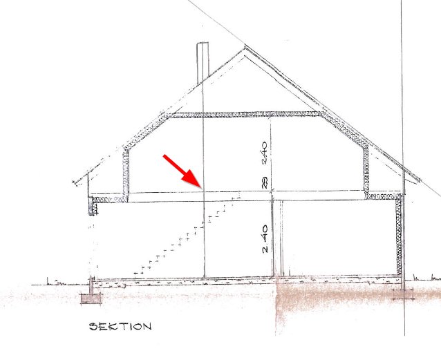
The roof truss beam starts a bit in on the stairs if you look from outside the house, meaning it must be supported quite early inside the outer wall. I'm not sure how it's done and how it looks further inside the house. I have assumed that it instead runs exactly in line with the edge of the stairs. The one that's cut is the intermediate beam between the stairs and the next beam, I'm guessing like this, in a completely amateurish way. Roof trusses in red, intermediate beam in blue. Don't look too closely at the scale and proportions
Is there a supporting post under the heavy beam, in the corner where the beam and stairs end?
It should be possible to have a transition between the two trusses if the wall under the stairs (the post) has a load-bearing function, but I don't dare to advise on load-bearing parts. You should have someone with construction knowledge assess the whole situation.
I feel that the stove installer should handle it if they have arbitrarily cut a load-bearing beam. If you get a professional opinion, you'll have better grounds to get compensation, but also the knowledge of what it looks like and what needs to be done to ensure it is correctly addressed.
Unbelievable that the stove installer doesn't realize he's on thin ice. He's taken on something he doesn't master and is actually liable for damages. The cut floor joist must, as @Oldboy points out, be transferred to the adjacent joists. This requires the joist layer to be opened slightly, from above or below. Since smoke channels need to have a certain distance from load-bearing constructions, the problem with transferring is very recurrent.
Now I have found out that roof modifications/structural alterations also need to be reported to the municipality, so that needs to be handled as well. Waiting for a response from the stove company and then we'll see where it goes. It seems quite established that it needs to be structurally altered anyway.
If you look at the image in post #9, it also seems possible that the beam of the truss by the stairs is supported against the now cut beam. The lower beam of the trusses has a function to support the floor, but also serves as a tensile load from the truss. The truss is "trying" to pull out the beam. If it is supported against the cut beam, the truss will pull out the beam and push the outer wall outward.
If you look at the picture in post #9, it also seems possible that the rafter's beam at the staircase is offset against the now cut beam. The rafters' lower beam serves partly to support the floor, but there is also a tension load from the rafter. The rafter "tries" to pull the beam out. If it is then offset against the cut beam, the rafter will pull the beam out and bend the outer wall outward.,
Good point. This needs to be investigated as soon as possible, as the floor will need to be taken up sooner or later to sort this out.
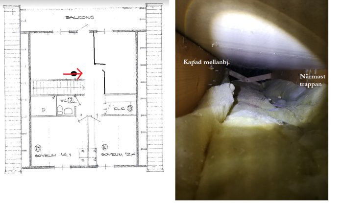
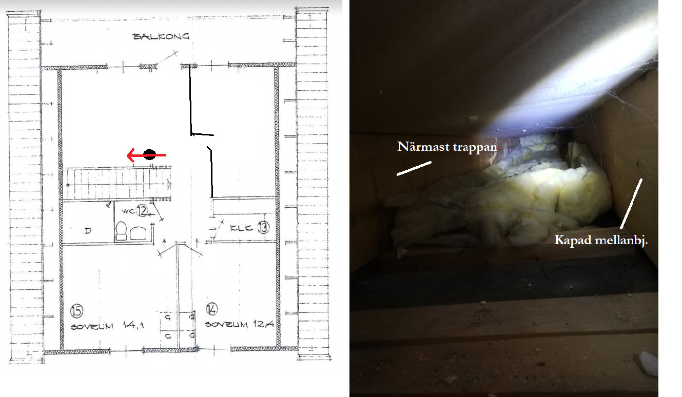
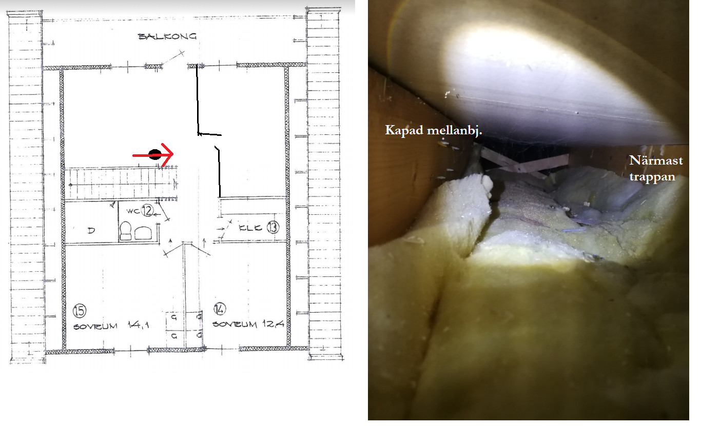
Managed to insert a camera and flashlight into the gap between the beam closest to the stairs and the one that's cut. I couldn't see any offsets. Towards the outer wall (first image), it looks like it's open towards the insulation against the crawl space. Inward, however, there are some kind of crisscrossed boards which I don't know what they are. You only see a bit in there, not all the way.
Vi vill skicka notiser för ämnen du bevakar och händelser som berör dig.


")