
Hello Can someone help me decipher what is circled on the attached drawing/image? What does 45x195 T20 between each rafter mean? I understand the dimensions but not "between each rafter." What does "post in wall" mean? I guess it's some sort of reinforcement? Then these wall bands... 45x120 on its edge and then on its side, what type of wall band is that? (I'm a complete novice when it comes to building technology though) My house was built in 1980 and I thought the entire house frame consisted of 45x95 studs or something. But maybe it's only the interior walls that are those dimensions? The house frame might consist of 45x120? I can attach additional drawings if desired.
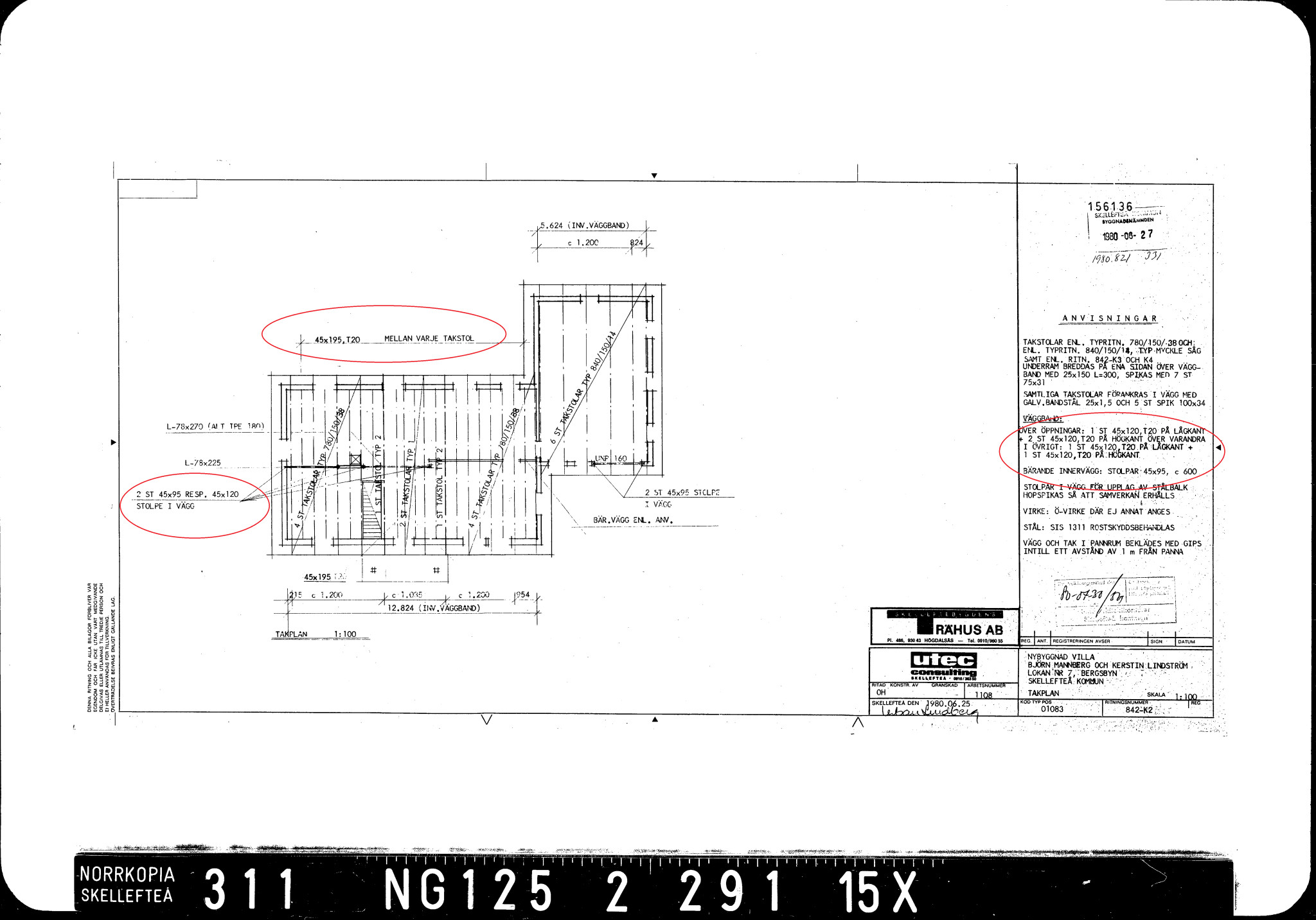


The rafters are 120 cm apart, so to reduce the distance to 60 cm, an extra stud has been placed between each rafter to, for example, attach the ceiling to.R roband915 said:
45x95 is too weak to construct load-bearing parts from.
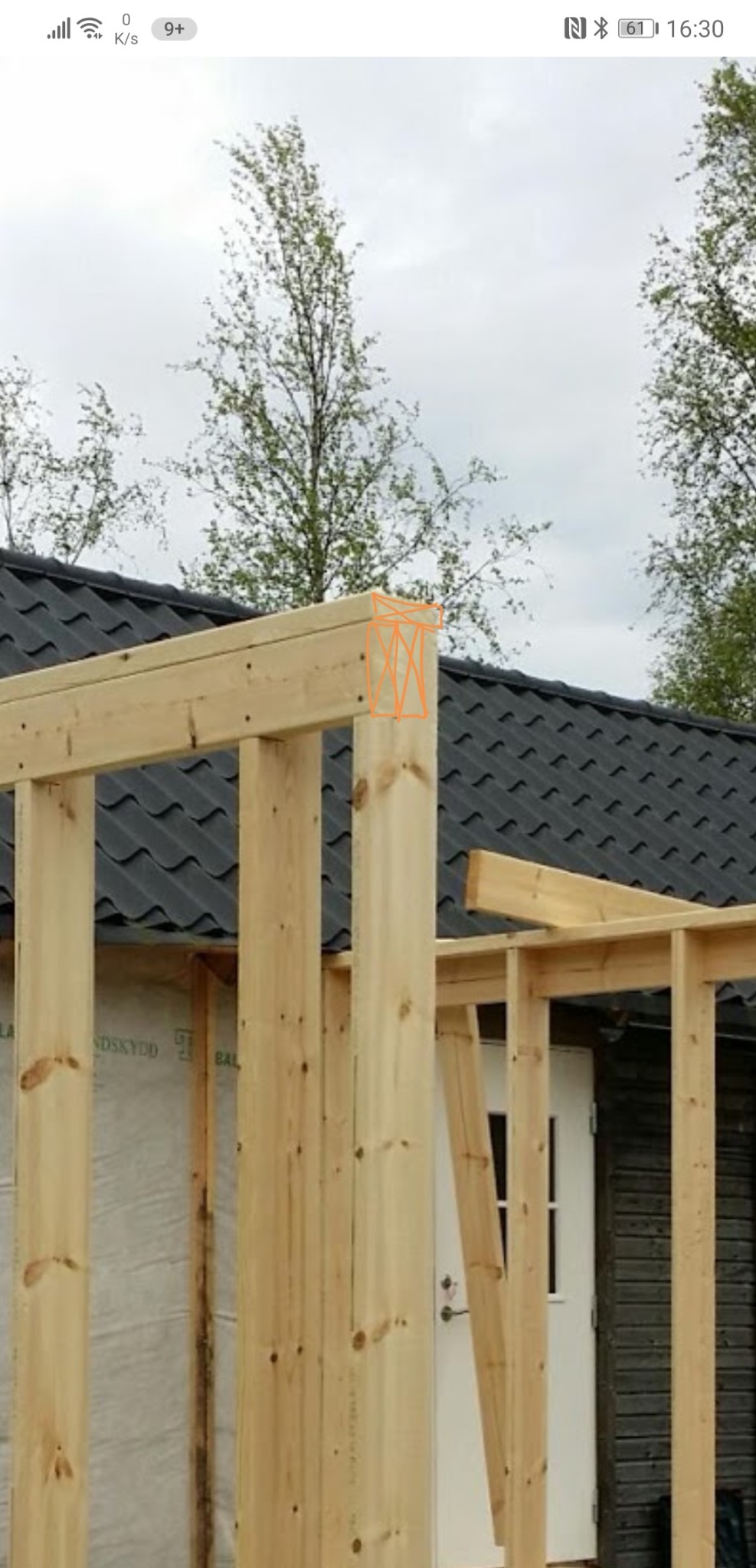
It's a hammarband and bärlina. The upright one (bärlina) bears the vertical load from the rafters, and the one lying down (hammarband) absorbs horizontal forces to prevent the walls from being pushed outward.R roband915 said:
https://sv.m.wikipedia.org/wiki/Hammarband
Last edited:
Must begin by stating that having some basic knowledge is good if you are the only one who will build the house. Otherwise, I strongly recommend getting help. The attachment method is an example that is just as important as dimensioning but which not everyone can usually handle.
T20 is a type of strength class (old). Buy in timber class c24 to be safe.
The posts are simply to take down the forces on the glulam beam. 2 pcs 45x95 screwed together vs 2 pcs 45x120 on the one in the middle.
All exterior walls are built in 45x120. Normally with 1 standing 45x120 recessed and 1 lying 45x120.
Over windows and doors, you place two pieces instead.
T20 is a type of strength class (old). Buy in timber class c24 to be safe.
The posts are simply to take down the forces on the glulam beam. 2 pcs 45x95 screwed together vs 2 pcs 45x120 on the one in the middle.
All exterior walls are built in 45x120. Normally with 1 standing 45x120 recessed and 1 lying 45x120.
Over windows and doors, you place two pieces instead.

I can almost promise everyone reading this thread that I will never build a house  However, I'm better at drawing in 3D, and my intention was to draw up the house as accurately as I can in order to learn a bit about how a house is built. Or at least what my house looks like. All help is invaluable, so a big thank you!
However, I'm better at drawing in 3D, and my intention was to draw up the house as accurately as I can in order to learn a bit about how a house is built. Or at least what my house looks like. All help is invaluable, so a big thank you!Usually, exterior walls are thicker than interior walls, and considering the drawing indicates a 45x120 laid flat and one upright, you likely have a 45x120 as the exterior wall frame. However, it wouldn't have been impossible for you to have 45x95 even in the exterior walls since it's an old house. My house is a winterized summer cottage from 1971, and the wall frames are 56mm with a load-bearing length (distance between the two long walls) of 6m, so it is possible to build with more slender timber, but probably no one does that today. I don't even know if it's possible if you have to meet all the energy requirements, etc.R roband915 said:
I'm having a bit of trouble finding anything on the drawings about how the floor is constructed. The floor on the ground floor (it's a two-story house) isn't laid directly on the concrete slab, I assume. I guess you use vertical studs in some way and then add insulation before finishing with what is called floor chipboard (Particleboard type?)?
Or is it me who can't interpret the drawing again?
Or is it me who can't interpret the drawing again?
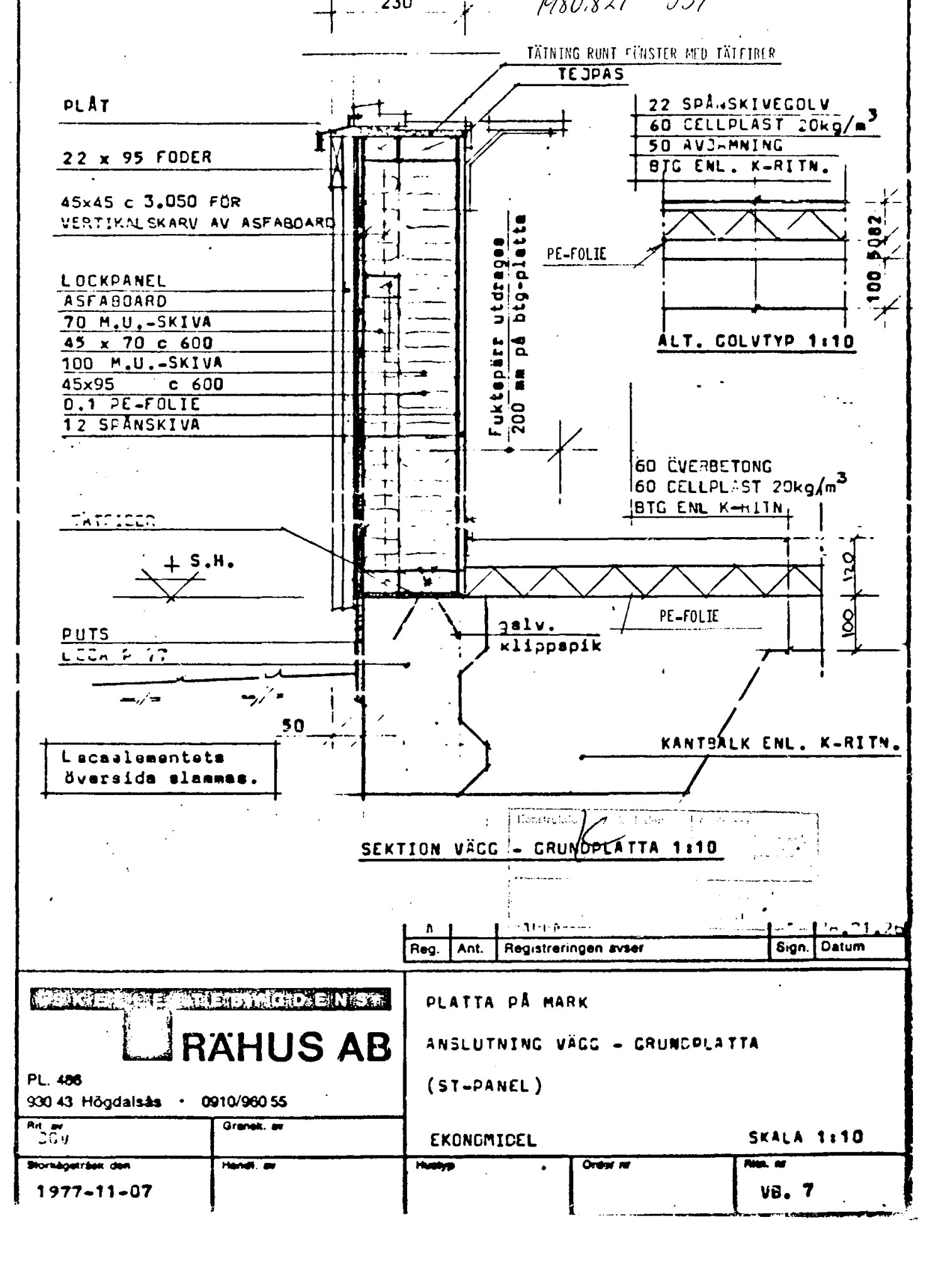
Hard to see what's written by the floor, but I interpret it as if there is something between the slab and the chipboards that is 60cm high. Not sure about that though.R roband915 said:I'm having a little trouble finding something on the drawings about how the floor is constructed. The floor on the ground floor (It's a two-story house) is probably not laid directly on the concrete slab, I think. I guess you frame with vertical studs in some way and then add insulation before finishing with what is called golvspån (chipboard kind of?)?
Or is it that I can't read the drawing again?
Regarding the walls, it looks like you have a frame of 45x95 and 45x70 on the outside of that. I suspect these are staggered wall studs to reduce thermal bridges.
Looking at it on the phone, it's hard to say, but it seems to me that both are vertical. Hopefully, they are not assembled together but are shifted so that the 70-rules stand with cc 60 cm and the 95-rules do too, but if you look towards the wall, they stand with, for example, cc 30 cm, where you will see alternating 70 and 95.R roband915 said:
My respect for those of you who can build only grows bigger and bigger. My house frame is starting to look more like a slightly structured game of pick-up sticks, so we should be glad it's only in 3D
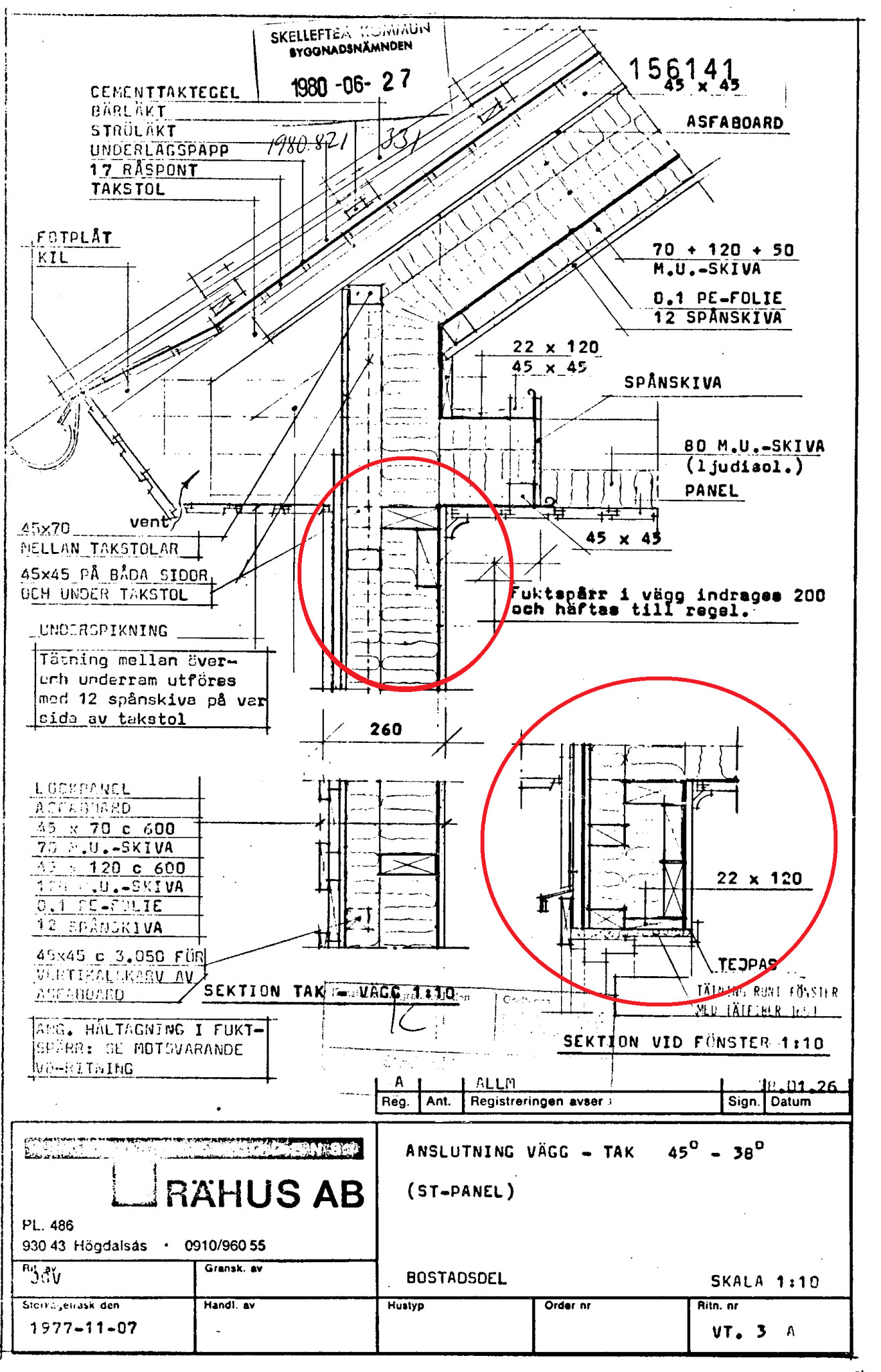
Do sill plates and top plates always have the same dimensions? In my case, for example, I seem to have a frame based on 45x95 and 45x70, but at the same time, I have top plates with the dimension 45x120. Can this be correct?
And according to the attached image, I have two studs (presumably 45x120) placed on top of each other(!). This is over openings and windows, I guess. Is this how it's built?
Do sill plates and top plates always have the same dimensions? In my case, for example, I seem to have a frame based on 45x95 and 45x70, but at the same time, I have top plates with the dimension 45x120. Can this be correct?
And according to the attached image, I have two studs (presumably 45x120) placed on top of each other(!). This is over openings and windows, I guess. Is this how it's built?
Yes, it looks a bit like a structured pick-up sticks until everything is finishedR roband915 said:


Now, I am a self-taught DIYer, but I would think that you generally have the same measurements on top plates and sill if it is built like your house, as it would be easiest if the whole frame has the same measurements on the same part of the wall. In this drawing, you appear to have 45x70+45x120 in the walls, while the previous drawing seemed to have 45x70+45x95 in the walls to confuse even more. One drawing is from '77 and the other from '80, so I have four guesses depending on whether everything was built at the same time and if it is a one- or two-story house. Option 1. The drawing from '77 is from a preliminary decision or similar, but the house wasn't built until '80, by which time they had managed to change certain parts of the house. Option 2. The ground floor was built in '77, and the upper floor was built in '80. Then the ground floor may have been built with 45x70+45x95 and the upper floor with 45x70+45x120, as it probably rests on parts of the old rafters. Option 3. The first part of the house was built in '77 with 45x70+45x95 in the walls, and then the house was extended in '80 with 45x70+45x120 in the walls. Option 4. Different walls in the house are built differently thick, so that one exterior wall can be 45x70+45x95, while another is 45x70+45x120. Presumably, the long walls the rafters rest on should be 45x70+45x120, and the rest 45x70+45x95.R roband915 said:
I've only built my "garage," and I haven't done it that way, but I do have an embedded support beam under the top plate to better distribute the weight from the rafters across the entire wall. My garage is also uninsulated with a metal roof, so it resembles more of a barn in terms of building method. But when building larger and heavier constructions, it wouldn't surprise me if you have two studs on edge on top of each other above doors and windows since it involves entirely different loads than in my case.R roband915 said:
Click here to reply